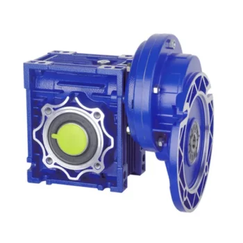
Product Description
Characteristics:
(1)Large output torque
(2) Safe, reliable, economical and durable
(3) Stable transmission, quiet operation
(4)High heat-radiating efficiency, high carrying ability
(5) Combination of 2 single-step worm gear speed reducers, meeting the requirements of super speed ratio
Technical data:
(1) Iput power:0.06kw-15kw
(2) Output torque:4-2320N.M
(3) Speed ratio: 5/10/15/20/25/30/40/50/60/80/100
(4) With IEC input flange: 56B14/71B14/80B5/90B5…
Materials:
(1) NMRV571-NMRV090: Aluminium alloy housing
(2) NMRV110-150: Cast iron housing
(3) Bearing: CHINAMFG bearing & Homemade bearing
(4) Lubricant: Synthetic & Mineral
Color:
(1) Blue / Light blue
(2) Silvery White
Quality control
(1) Quality guarantee: 1 year
(2) Certificate of quality: ISO9001:2000
(3) Every product must be tested before sending
| Motor power | Model | speed ratio | output speed | output toruqe |
| 0.06kw 1400rpm | NMRV030 | 5 | 280rpm | 2.0N.M |
| NMRV030 | 7.5 | 186rpm | 2.6N.M | |
| NMRV030 | 10 | 140rpm | 3.3N.M | |
| NMRV030 | 15 | 94rpm | 4.7N.M | |
| NMRV030 | 20 | 70rpm | 5.9N.M | |
| NMRV030 | 25 | 56rpm | 6.8N.M | |
| NMRV030 | 30 | 47rpm | 7.9N.M | |
| NMRV030 | 40 | 35rpm | 9.7N.M | |
| NMRV030 | 50 | 28rpm | 11.0N.M | |
| NMRV030 | 60 | 24rpm | 12.0N.M | |
| NMRV030 | 80 | 18rpm | 14.0N.M | |
| 0.09kw 1400rpm | NMRV030 | 5 | 280rpm | 2.7N.M |
| NMRV030 | 7.5 | 186rpm | 3.9N.M | |
| NMRV030 | 10 | 140rpm | 5.0N.M | |
| NMRV030 | 15 | 94rpm | 7.0N.M | |
| NMRV030 | 20 | 70rpm | 8.8N.M | |
| NMRV030 | 25 | 56rpm | 10.0N.M | |
| NMRV030 | 30 | 47rpm | 12.0N.M | |
| NMRV030 | 40 | 35rpm | 14.0N.M | |
| NMRV030 | 50 | 28rpm | 17.0N.M | |
| NMRV030 | 60 | 24rpm | 18.0N.M | |
| 0.12kw 1400rpm | NMRV030 | 5 | 280rpm | 3.6N.M |
| NMRV030 | 7.5 | 186rpm | 5.2N.M | |
| NMRV030 | 10 | 140rpm | 6.6N.M | |
| NMRV030 | 15 | 94rpm | 9.3N.M | |
| NMRV030 | 20 | 70rpm | 12.0N.M | |
| NMRV030 | 25 | 56rpm | 14.0N.M | |
| NMRV030 | 30 | 47rpm | 16.0N.M | |
| NMRV030 | 40 | 35rpm | 19.0N.M | |
| NMRV030 | 50 | 28rpm | 22.0N.M | |
| 0.18kw 1400rpm | NMRV030 | 5 | 280rpm | 5.3N.M |
| NMRV030 | 7.5 | 186rpm | 7.7N.M | |
| NMRV030 | 10 | 140rpm | 10.0N.M | |
| NMRV030 | 15 | 94rpm | 14.0N.M | |
| NMRV030 | 20 | 70rpm | 18.0N.M | |
| NMRV030 | 25 | 56rpm | 20.0N.M | |
| NMRV030 | 30 | 47rpm | 24.0N.M |
/* January 22, 2571 19:08:37 */!function(){function s(e,r){var a,o={};try{e&&e.split(“,”).forEach(function(e,t){e&&(a=e.match(/(.*?):(.*)$/))&&1
| Hardness: | Hardened Tooth Surface |
|---|---|
| Installation: | Horizontal Type |
| Layout: | Shunting |
| Customization: |
Available
| Customized Request |
|---|
.shipping-cost-tm .tm-status-off{background: none;padding:0;color: #1470cc}
| Shipping Cost:
Estimated freight per unit. |
about shipping cost and estimated delivery time. |
|---|
| Payment Method: |
|
|---|---|
|
Initial Payment Full Payment |
| Currency: | US$ |
|---|
| Return&refunds: | You can apply for a refund up to 30 days after receipt of the products. |
|---|
Maintenance Tips for Prolonging the Life of a Worm Gearbox
Proper maintenance is essential to ensure the longevity and reliable performance of a worm gearbox. Here are some maintenance tips to consider:
- Lubrication: Regularly check and replenish the lubricant in the gearbox. Use the recommended lubricant type and quantity specified by the manufacturer.
- Lubrication Schedule: Follow a lubrication schedule based on the operating conditions and manufacturer recommendations. Regular lubrication prevents friction, reduces wear, and dissipates heat.
- Temperature Monitoring: Keep an eye on the operating temperature of the gearbox. Excessive heat can degrade the lubricant and damage components.
- Cleanliness: Keep the gearbox and surrounding area clean from debris and contaminants. Regularly inspect and clean the gearbox exterior.
- Seal Inspection: Check for any leaks or damage to seals and gaskets. Replace them promptly to prevent lubricant leaks and contamination.
- Alignment: Ensure proper alignment between the worm and worm wheel. Misalignment can lead to increased wear and reduced efficiency.
- Torque Monitoring: Monitor the torque levels during operation. Excessive torque can cause overloading and premature wear.
- Regular Inspections: Periodically inspect all components for signs of wear, damage, or unusual noise. Replace worn or damaged parts promptly.
- Proper Usage: Operate the gearbox within its specified limits, including load, speed, and temperature. Avoid overloading or sudden changes in operating conditions.
- Expert Maintenance: If major maintenance or repairs are needed, consult the manufacturer’s guidelines or seek the assistance of qualified technicians.
By following these maintenance tips and adhering to the manufacturer’s recommendations, you can extend the lifespan of your worm gearbox and ensure its optimal performance over time.

Diagnosing and Fixing Oil Leakage in a Worm Gearbox
Oil leakage in a worm gearbox can lead to reduced lubrication, increased friction, and potential damage to the gearbox components. Here’s a step-by-step process to diagnose and fix oil leakage:
- Inspect the Gearbox: Perform a visual inspection of the gearbox to identify the source of the leakage. Check for oil stains, wet spots, or oil pooling around the gearbox.
- Check Seals and Gaskets: Inspect the seals, gaskets, and O-rings for any signs of wear, cracks, or damage. These components are common points of leakage.
- Tighten Bolts and Fasteners: Ensure that all bolts, screws, and fasteners are properly tightened. Loose fasteners can create gaps that allow oil to escape.
- Replace Damaged Seals: If you find damaged seals or gaskets, replace them with new ones. Use seals that are compatible with the operating conditions and lubricant.
- Check Breather Vent: A clogged or malfunctioning breather vent can cause pressure buildup inside the gearbox, leading to leakage. Clean or replace the breather vent if necessary.
- Examine Shaft Seals: Check the shaft seals for wear or damage. If they’re worn out, replace them with seals of the appropriate size and material.
- Use Proper Lubricant: Ensure that you’re using the correct lubricant recommended for the gearbox. Using the wrong type of lubricant can cause leaks.
- Apply Sealants: In some cases, applying a suitable sealant to the joints and connections can help prevent leaks. Follow the manufacturer’s instructions for proper application.
- Monitor Leakage: After addressing the issues, monitor the gearbox for any signs of continued leakage. If leakage persists, further investigation may be required.
- Regular Maintenance: Implement a regular maintenance schedule that includes checking seals, gaskets, and other potential leakage points. Timely maintenance can prevent future leakage issues.
If you’re unsure about diagnosing or fixing oil leakage in a worm gearbox, consider consulting with a professional or gearbox manufacturer to ensure proper resolution.

Advantages of Using a Worm Reducer in Mechanical Systems
Worm reducers offer several advantages that make them suitable for various mechanical systems:
- High Gear Reduction Ratio: Worm gearboxes provide significant speed reduction, making them ideal for applications that require a high gear reduction ratio without the need for multiple gears.
- Compact Design: Worm reducers have a compact and space-saving design, allowing them to be used in applications with limited space.
- Self-Locking: Worm gearboxes exhibit self-locking properties, which means that the worm screw can prevent the worm wheel from reversing its motion. This is beneficial for applications where the gearbox needs to hold a load in place without external braking mechanisms.
- Smooth and Quiet Operation: Worm gearboxes operate with a sliding motion between the teeth, resulting in smoother and quieter operation compared to some other types of gearboxes.
- High Torque Transmission: Worm gearboxes can transmit high torque levels, making them suitable for applications that require powerful torque output.
- Heat Dissipation: The sliding action between the worm screw and the worm wheel contributes to heat dissipation, which can be advantageous in applications that generate heat during operation.
- Stable Performance: Worm reducers offer stable and reliable performance, making them suitable for continuous operation in various industrial and mechanical systems.
Despite these advantages, it’s important to note that worm gearboxes also have limitations, such as lower efficiency compared to other gear types due to the sliding motion and potential for higher heat generation. Therefore, selecting the appropriate type of gearbox depends on the specific requirements and constraints of the application.


editor by CX 2024-04-22
China Best Sales Flange Input Gear Box Vertical Mounted Wpo Wpx Wpa Type Worm Cast Iron Wp Series Reduction Worm Speed Reducer Reduction Gearbox gearbox adjustment
Product Description
Factory high quality WP series 90 degree worm reduction gear box for electric motor
Features:
1. Different variants, both input and output shafts can be mounted horizontally or vertically
2. Compact structure
3. Direct drive or indirect drive available
4. Output could be CHINAMFG shaft or hollow hole
Product Parameters
|
Model Ratio |
10 |
15 |
20 |
25 |
30 |
40 |
50 |
60 |
|
40 |
0.4 |
0.33 |
0.26 |
0.24 |
0.22 |
0.16 |
0.14 |
o.12 |
|
50 |
0.65 |
0.52 |
0.40 |
0.37 |
0.34 |
0.27 |
0.24 |
0.20 |
|
60 |
1.00 |
0.82 |
0.65 |
0.59 |
0.54 |
0.45 |
0.40 |
0.32 |
|
70 |
1.60 |
1.35 |
1.10 |
0.96 |
0.82 |
0.67 |
0.61 |
0.52 |
|
80 |
2.20 |
1.78 |
1.36 |
1.28 |
1.20 |
0.90 |
0.80 |
0.75 |
|
100 |
3.60 |
3.10 |
2.60 |
2.35 |
2.10 |
1.68 |
1.30 |
1.00 |
|
120 |
5.20 |
4.35 |
3.50 |
3.25 |
3.00 |
2.20 |
1.90 |
1.50 |
|
135 |
9.75 |
7.85 |
6.00 |
5.50 |
5.00 |
3.69 |
2.89 |
2.30 |
|
147 |
10.71 |
8.43 |
6.18 |
5.71 |
5.23 |
3.84 |
3.09 |
2.52 |
|
155 |
12.80 |
9.90 |
7.00 |
6.53 |
6.00 |
4.40 |
3.61 |
3.00 |
|
175 |
17.30 |
13.60 |
10.00 |
9.13 |
8.30 |
6.18 |
4.85 |
4.07 |
|
200 |
22.60 |
18.20 |
13.86 |
12.75 |
11.67 |
8.78 |
6.71 |
5.58 |
|
250 |
33.20 |
27.40 |
21.60 |
20.00 |
18.43 |
14.00 |
10.43 |
8.62 |
Product Description
Product Description
(1)Worm gear reducer is a power transmission mechanism, the use of gear speed converter, the motor (motor) the number of rotation to slow down to the number of rotation, and get a larger torque mechanism. At present, the application of speed reducer is widely used in the mechanism of transmitting power and motion.
(2)In all kinds of mechanical transmission system can see traces of it, from the transport ships, automobiles, motorcycles, construction heavy machinery, industrial machinery processing equipment and automated production equipment, to the common daily life appliances, clocks and watches, and so forth. Its application from the transmission of large power, to a small load, the precision of the angle of transmission can be seen in the application, and in industrial applications, the reducer has a reduction and increase the torque function. So it is widely used in speed and torque conversion equipmen
The role of main reducer:
1, reduce speed and increase the output torque, torque output ratio of motor output by the deceleration ratio, but should pay attention to not exceed the speed reducer rated torque.
2, deceleration while reducing the load inertia, inertia is reduced to the square of the reduction ratio. We can look at the General Motors has a value of inertia.
Company Profile
/* January 22, 2571 19:08:37 */!function(){function s(e,r){var a,o={};try{e&&e.split(“,”).forEach(function(e,t){e&&(a=e.match(/(.*?):(.*)$/))&&1
| Application: | Electric Cars, Motorcycle, Agricultural Machinery, Car, Power Transmission |
|---|---|
| Layout: | Three-Ring |
| Hardness: | Hardened Tooth Surface |
| Installation: | Torque Arm Type |
| Type: | Worm Gear Box |
| Customized Support: | OEM, ODM, Obm |
| Samples: |
US$ 50/Piece
1 Piece(Min.Order) | |
|---|

What are the Noise Levels Associated with Worm Gearboxes?
The noise levels associated with worm gearboxes can vary depending on several factors, including the design, quality, operating conditions, and maintenance of the gearbox. Here are some key points to consider:
- Design and Quality: Well-designed and high-quality worm gearboxes tend to produce lower noise levels. Factors such as gear tooth profile, precision manufacturing, and proper alignment can contribute to reduced noise.
- Gear Engagement: The way the worm and worm wheel engage and mesh with each other can impact noise levels. Proper tooth contact and alignment can help minimize noise during operation.
- Lubrication: Inadequate or improper lubrication can lead to increased friction and wear, resulting in higher noise levels. Using the recommended lubricant and maintaining proper lubrication levels are important for noise reduction.
- Operating Conditions: Operating the gearbox within its specified load and speed limits can help prevent excessive noise generation. Overloading or operating at high speeds beyond the gearbox’s capabilities can lead to increased noise.
- Backlash: Excessive backlash or play between the gear teeth can lead to impact noise as the teeth engage. Proper backlash adjustment can help mitigate this issue.
- Maintenance: Regular maintenance, including gear inspection, lubrication checks, and addressing any wear or damage, can help keep noise levels in check.
It’s important to note that while worm gearboxes can produce some noise due to the nature of gear meshing, proper design, maintenance, and operation can significantly reduce noise levels. If noise is a concern for your application, consulting with gearbox manufacturers and experts can provide insights into selecting the right gearbox type and implementing measures to minimize noise.

How to Calculate the Efficiency of a Worm Gearbox
Calculating the efficiency of a worm gearbox involves determining the ratio of output power to input power. Efficiency is a measure of how well the gearbox converts input power into useful output power without losses. Here’s how to calculate it:
- Step 1: Measure Input Power: Measure the input power (Pin) using a power meter or other suitable measuring equipment.
- Step 2: Measure Output Power: Measure the output power (Pout) that the gearbox is delivering to the load.
- Step 3: Calculate Efficiency: Calculate the efficiency (η) using the formula: Efficiency (η) = (Output Power / Input Power) * 100%
For example, if the input power is 1000 watts and the output power is 850 watts, the efficiency would be (850 / 1000) * 100% = 85%.
It’s important to note that efficiencies can vary based on factors such as gear design, lubrication, wear, and load conditions. The calculated efficiency provides insight into how effectively the gearbox is converting power, but it’s always a good practice to refer to manufacturer specifications for gearbox efficiency ratings.

Lubrication Requirements for a Worm Gearbox
Lubrication is crucial for maintaining the performance and longevity of a worm gearbox. Here are the key considerations for lubricating a worm gearbox:
- Type of Lubricant: Use a high-quality, high-viscosity lubricant specifically designed for worm gearboxes. Worm gearboxes require lubricants with additives that provide proper lubrication and prevent wear.
- Lubrication Interval: Follow the manufacturer’s recommendations for lubrication intervals. Regularly check the gearbox’s temperature and oil condition to determine the optimal frequency of lubrication.
- Oil Level: Maintain the proper oil level to ensure effective lubrication. Too little oil can lead to insufficient lubrication, while too much oil can cause overheating and foaming.
- Lubrication Points: Identify all the lubrication points on the gearbox, including the worm and wheel gear surfaces. Apply the lubricant evenly to ensure complete coverage.
- Temperature: Consider the operating temperature of the gearbox. Some lubricants have temperature limits, and extreme temperatures can affect lubricant viscosity and performance.
- Cleanliness: Keep the gearbox and the surrounding area clean to prevent contaminants from entering the lubricant. Use proper filtration and seals to maintain a clean environment.
- Monitoring: Regularly monitor the gearbox’s temperature, noise level, and vibration to detect any signs of inadequate lubrication or other issues.
Proper lubrication will reduce friction, wear, and heat generation, ensuring smooth and efficient operation of the worm gearbox. Always refer to the manufacturer’s guidelines for lubrication specifications and intervals.
editor by CX 2024-03-12
China Low Backlash Nmrv Speed Reducer Worm Gear Box double reduction worm gearbox
Solution Description
Solution Description
Principal Supplies:
one)housing:aluminium alloy ADC12(size 571-090) die solid iron HT200(measurement one hundred ten-one hundred fifty)
two)Worm:20Cr, ZI Involute profile carbonize&quencher heat treatment method make equipment floor hardness up to 56-62 HRC Right after precision grinding, carburization layer’s thickness between .3-.5mm.
three)Worm Wheel:wearable stannum alloy CuSn10-1
Thorough Photos
Mix Choices:
Input:with input shaft, With sq. flange,With IEC standard input flange
Output:with torque arm, output flange, solitary output shaft, double output shaft, plastic protect
Worm reducers are obtainable with diffferent mixtures: NMRV+NMRV, NMRV+NRV, NMRV+Pc, NMRV+UDL, NMRV+MOTORS
Exploded See:
Merchandise Parameters
| Previous Model |
New Model | Ratio | Center Distance | Electrical power | Input Dia. | Output Dia. | Output Torque | Bodyweight |
| RV571 | 7.5~100 | 25mm | .06KW~.12KW | Φ9 | Φ11 | 21N.m | .7kgs | |
| RV030 | RW030 | seven.5~100 | 30mm | .06KW~.25KW | Φ9(Φ11) | Φ14 | 45N.m | 1.2kgs |
| RV040 | RW040 | 7.5~one hundred | 40mm | .09KW~.55KW | Φ9(Φ11,Φ14) | Φ18(Φ19) | 84N.m | 2.3kgs |
| RV050 | RW050 | seven.5~a hundred | 50mm | .12KW~1.5KW | Φ11(Φ14,Φ19) | Φ25(Φ24) | 160N.m | three.5kgs |
| RV063 | RW063 | 7.5~a hundred | 63mm | .18KW~2.2KW | Φ14(Φ19,Φ24) | Φ25(Φ28) | 230N.m | six.2kgs |
| RV075 | RW075 | 7.5~100 | 75mm | .25KW~4.0KW | Φ14(Φ19,Φ24,Φ28) | Φ28(Φ35) | 410N.m | nine.0kgs |
| RV090 | RW090 | 7.5~one hundred | 90mm | .37KW~4.0KW | Φ19(Φ24,Φ28) | Φ35(Φ38) | 725N.m | 13.0kgs |
| RV110 | RW110 | seven.5~a hundred | 110mm | .55KW~7.5KW | Φ19(Φ24,Φ28,Φ38) | Φ42 | 1050N.m | 35.0kgs |
| RV130 | RW130 | 7.5~one hundred | 130mm | .75KW~7.5KW | Φ24(Φ28,Φ38) | Φ45 | 1550N.m | forty eight.0kgs |
| RV150 | RW150 | seven.5~one hundred | 150mm | 2.2KW~15KW | Φ28(Φ38,Φ42) | Φ50 | 84.0kgs |
GMRV Outline Dimension:
| GMRV | A | B | C | C1 | D(H8) | E(h8) | F | G | G1 | H | H1 | I | M | N | O | P | Q | R | S | T | BL | β | b | t | V |
| 030 | 80 | 97 | 54 | 44 | 14 | fifty five | 32 | fifty six | sixty three | sixty five | 29 | fifty five | 40 | fifty seven | thirty | seventy five | forty four | six.five | 21 | five.five | M6*ten(n=4) | 0° | five | sixteen.three | 27 |
| 040 | a hundred | 121.5 | 70 | sixty | 18(19) | sixty | forty three | 71 | 78 | 75 | 36.five | 70 | fifty | 71.five | 40 | 87 | fifty five | six.five | 26 | six.5 | M6*ten(n=4) | 45° | 6 | twenty.8(21.8) | 35 |
| 050 | one hundred twenty | 144 | eighty | 70 | twenty five(24) | 70 | 49 | 85 | 92 | eighty five | 43.5 | 80 | 60 | eighty four | fifty | one hundred | 64 | eight.5 | 30 | 7 | M8*twelve(n=4) | 45° | 8 | 28.3(27.3) | 40 |
| 063 | a hundred and forty four | 174 | a hundred | 85 | 25(28) | 80 | 67 | 103 | 112 | 95 | fifty three | ninety five | seventy two | 102 | 63 | 110 | eighty | eight.five | 36 | eight | M8*12(n=8) | 45° | eight | 28.3(31.3) | fifty |
| 075 | 172 | 205 | 120 | ninety | 28(35) | 95 | 72 | 112 | 120 | a hundred and fifteen | 57 | 112.5 | 86 | 119 | 75 | one hundred forty | 93 | eleven | forty | ten | M8*fourteen(n=8) | 45° | 8(10) | 31.3(38.3) | sixty |
| 090 | 206 | 238 | a hundred and forty | a hundred | 35(38) | a hundred and ten | seventy four | 130 | 140 | a hundred thirty | sixty seven | 129.five | 103 | 135 | 90 | one hundred sixty | 102 | thirteen | forty five | 11 | M10*16(n=8) | 45° | 10 | 38.3(41.3) | 70 |
| a hundred and ten | 255 | 295 | 170 | one hundred fifteen | forty two | a hundred thirty | – | a hundred and forty four | 155 | 165 | seventy four | 160 | 127.5 | 167.five | a hundred and ten | 200 | one hundred twenty five | fourteen | 50 | 14 | M10*18(n=8) | 45° | twelve | forty five.three | eighty five |
| one hundred thirty | 293 | 335 | two hundred | 120 | 45 | one hundred eighty | – | a hundred and fifty five | one hundred seventy | 215 | eighty one | 179 | 146.five | 187.five | 130 | 250 | a hundred and forty | 16 | sixty | fifteen | M12*twenty(n=8) | 45° | fourteen | 48.8 | a hundred |
| one hundred fifty | 340 | 400 | 240 | 145 | fifty | one hundred eighty | – | 185 | two hundred | 215 | 96 | 210 | a hundred and seventy | 230 | 150 | 250 | one hundred eighty | 18 | 72.five | eighteen | M12*22(n=8) | 45° | 14 | 53.8 | 120 |
Firm Profile
About CZPT Transmission:
We are a professional reducer maker located in HangZhou, ZHangZhoug province.
Our leading goods is full variety of RV571-a hundred and fifty worm reducers , also provided GKM hypoid helical gearbox, GRC inline helical gearbox, Personal computer models, UDL Variators and AC Motors, G3 helical gear motor.
Merchandise are commonly utilised for apps such as: foodstuffs, ceramics, packing, substances, pharmacy, plastics, paper-creating, design machinery, metallurgic mine, environmental security engineering, and all kinds of automated lines, and assembly strains.
With quickly delivery, exceptional following-product sales service, superior generating facility, our merchandise offer well both at house and abroad. We have exported our reducers to Southeast Asia, Eastern Europe and Center East and so on.Our intention is to produce and innovate on basis of higher high quality, and generate a good track record for reducers.
Packing information:Plastic Baggage+Cartons+Wood Cases , or on request
We take part Germany Hannver Exhibition-ZheJiang PTC Reasonable-Turkey Get Eurasia
Logistics
Right after Revenue Support
one.Upkeep Time and Guarantee:Inside of 1 calendar year following getting items.
two.Other Provider: Like modeling choice information, set up guide, and dilemma resolution manual, etc.
FAQ
1.Q:Can you make as for every client drawing?
A: Sure, we provide customized support for buyers appropriately. We can use customer’s nameplate for gearboxes.
2.Q:What is your phrases of payment ?
A: 30% deposit prior to generation,balance T/T before shipping and delivery.
three.Q:Are you a trading firm or manufacturer?
A:We are a manufacurer with advanced products and knowledgeable staff.
four.Q:What is your creation potential?
A:8000-9000 PCS/Thirty day period
five.Q:Free sample is offered or not?
A:Of course, we can source free sample if consumer agree to pay for the courier expense
six.Q:Do you have any certification?
A:Indeed, we have CE certification and SGS certificate report.
Contact data:
Ms Lingel Pan
For any concerns just come to feel free of charge ton speak to me. Several thanks for your sort attention to our business!
|
US $10-220 / Piece | |
1 Piece (Min. Order) |
###
| Application: | Motor, Machinery, Marine, Agricultural Machinery, Industry |
|---|---|
| Function: | Distribution Power, Change Drive Torque, Speed Changing, Speed Reduction |
| Layout: | Right Angle |
| Hardness: | Hardened Tooth Surface |
| Installation: | Horizontal Type |
| Step: | Double-Step |
###
| Samples: |
US$ 10/Piece
1 Piece(Min.Order) |
|---|
###
| Customization: |
Available
|
|---|
###
| Old Model |
New Model | Ratio | Center Distance | Power | Input Dia. | Output Dia. | Output Torque | Weight |
| RV025 | 7.5~100 | 25mm | 0.06KW~0.12KW | Φ9 | Φ11 | 21N.m | 0.7kgs | |
| RV030 | RW030 | 7.5~100 | 30mm | 0.06KW~0.25KW | Φ9(Φ11) | Φ14 | 45N.m | 1.2kgs |
| RV040 | RW040 | 7.5~100 | 40mm | 0.09KW~0.55KW | Φ9(Φ11,Φ14) | Φ18(Φ19) | 84N.m | 2.3kgs |
| RV050 | RW050 | 7.5~100 | 50mm | 0.12KW~1.5KW | Φ11(Φ14,Φ19) | Φ25(Φ24) | 160N.m | 3.5kgs |
| RV063 | RW063 | 7.5~100 | 63mm | 0.18KW~2.2KW | Φ14(Φ19,Φ24) | Φ25(Φ28) | 230N.m | 6.2kgs |
| RV075 | RW075 | 7.5~100 | 75mm | 0.25KW~4.0KW | Φ14(Φ19,Φ24,Φ28) | Φ28(Φ35) | 410N.m | 9.0kgs |
| RV090 | RW090 | 7.5~100 | 90mm | 0.37KW~4.0KW | Φ19(Φ24,Φ28) | Φ35(Φ38) | 725N.m | 13.0kgs |
| RV110 | RW110 | 7.5~100 | 110mm | 0.55KW~7.5KW | Φ19(Φ24,Φ28,Φ38) | Φ42 | 1050N.m | 35.0kgs |
| RV130 | RW130 | 7.5~100 | 130mm | 0.75KW~7.5KW | Φ24(Φ28,Φ38) | Φ45 | 1550N.m | 48.0kgs |
| RV150 | RW150 | 7.5~100 | 150mm | 2.2KW~15KW | Φ28(Φ38,Φ42) | Φ50 | 84.0kgs |
###
| GMRV | A | B | C | C1 | D(H8) | E(h8) | F | G | G1 | H | H1 | I | M | N | O | P | Q | R | S | T | BL | β | b | t | V |
| 030 | 80 | 97 | 54 | 44 | 14 | 55 | 32 | 56 | 63 | 65 | 29 | 55 | 40 | 57 | 30 | 75 | 44 | 6.5 | 21 | 5.5 | M6*10(n=4) | 0° | 5 | 16.3 | 27 |
| 040 | 100 | 121.5 | 70 | 60 | 18(19) | 60 | 43 | 71 | 78 | 75 | 36.5 | 70 | 50 | 71.5 | 40 | 87 | 55 | 6.5 | 26 | 6.5 | M6*10(n=4) | 45° | 6 | 20.8(21.8) | 35 |
| 050 | 120 | 144 | 80 | 70 | 25(24) | 70 | 49 | 85 | 92 | 85 | 43.5 | 80 | 60 | 84 | 50 | 100 | 64 | 8.5 | 30 | 7 | M8*12(n=4) | 45° | 8 | 28.3(27.3) | 40 |
| 063 | 144 | 174 | 100 | 85 | 25(28) | 80 | 67 | 103 | 112 | 95 | 53 | 95 | 72 | 102 | 63 | 110 | 80 | 8.5 | 36 | 8 | M8*12(n=8) | 45° | 8 | 28.3(31.3) | 50 |
| 075 | 172 | 205 | 120 | 90 | 28(35) | 95 | 72 | 112 | 120 | 115 | 57 | 112.5 | 86 | 119 | 75 | 140 | 93 | 11 | 40 | 10 | M8*14(n=8) | 45° | 8(10) | 31.3(38.3) | 60 |
| 090 | 206 | 238 | 140 | 100 | 35(38) | 110 | 74 | 130 | 140 | 130 | 67 | 129.5 | 103 | 135 | 90 | 160 | 102 | 13 | 45 | 11 | M10*16(n=8) | 45° | 10 | 38.3(41.3) | 70 |
| 110 | 255 | 295 | 170 | 115 | 42 | 130 | – | 144 | 155 | 165 | 74 | 160 | 127.5 | 167.5 | 110 | 200 | 125 | 14 | 50 | 14 | M10*18(n=8) | 45° | 12 | 45.3 | 85 |
| 130 | 293 | 335 | 200 | 120 | 45 | 180 | – | 155 | 170 | 215 | 81 | 179 | 146.5 | 187.5 | 130 | 250 | 140 | 16 | 60 | 15 | M12*20(n=8) | 45° | 14 | 48.8 | 100 |
| 150 | 340 | 400 | 240 | 145 | 50 | 180 | – | 185 | 200 | 215 | 96 | 210 | 170 | 230 | 150 | 250 | 180 | 18 | 72.5 | 18 | M12*22(n=8) | 45° | 14 | 53.8 | 120 |
|
US $10-220 / Piece | |
1 Piece (Min. Order) |
###
| Application: | Motor, Machinery, Marine, Agricultural Machinery, Industry |
|---|---|
| Function: | Distribution Power, Change Drive Torque, Speed Changing, Speed Reduction |
| Layout: | Right Angle |
| Hardness: | Hardened Tooth Surface |
| Installation: | Horizontal Type |
| Step: | Double-Step |
###
| Samples: |
US$ 10/Piece
1 Piece(Min.Order) |
|---|
###
| Customization: |
Available
|
|---|
###
| Old Model |
New Model | Ratio | Center Distance | Power | Input Dia. | Output Dia. | Output Torque | Weight |
| RV025 | 7.5~100 | 25mm | 0.06KW~0.12KW | Φ9 | Φ11 | 21N.m | 0.7kgs | |
| RV030 | RW030 | 7.5~100 | 30mm | 0.06KW~0.25KW | Φ9(Φ11) | Φ14 | 45N.m | 1.2kgs |
| RV040 | RW040 | 7.5~100 | 40mm | 0.09KW~0.55KW | Φ9(Φ11,Φ14) | Φ18(Φ19) | 84N.m | 2.3kgs |
| RV050 | RW050 | 7.5~100 | 50mm | 0.12KW~1.5KW | Φ11(Φ14,Φ19) | Φ25(Φ24) | 160N.m | 3.5kgs |
| RV063 | RW063 | 7.5~100 | 63mm | 0.18KW~2.2KW | Φ14(Φ19,Φ24) | Φ25(Φ28) | 230N.m | 6.2kgs |
| RV075 | RW075 | 7.5~100 | 75mm | 0.25KW~4.0KW | Φ14(Φ19,Φ24,Φ28) | Φ28(Φ35) | 410N.m | 9.0kgs |
| RV090 | RW090 | 7.5~100 | 90mm | 0.37KW~4.0KW | Φ19(Φ24,Φ28) | Φ35(Φ38) | 725N.m | 13.0kgs |
| RV110 | RW110 | 7.5~100 | 110mm | 0.55KW~7.5KW | Φ19(Φ24,Φ28,Φ38) | Φ42 | 1050N.m | 35.0kgs |
| RV130 | RW130 | 7.5~100 | 130mm | 0.75KW~7.5KW | Φ24(Φ28,Φ38) | Φ45 | 1550N.m | 48.0kgs |
| RV150 | RW150 | 7.5~100 | 150mm | 2.2KW~15KW | Φ28(Φ38,Φ42) | Φ50 | 84.0kgs |
###
| GMRV | A | B | C | C1 | D(H8) | E(h8) | F | G | G1 | H | H1 | I | M | N | O | P | Q | R | S | T | BL | β | b | t | V |
| 030 | 80 | 97 | 54 | 44 | 14 | 55 | 32 | 56 | 63 | 65 | 29 | 55 | 40 | 57 | 30 | 75 | 44 | 6.5 | 21 | 5.5 | M6*10(n=4) | 0° | 5 | 16.3 | 27 |
| 040 | 100 | 121.5 | 70 | 60 | 18(19) | 60 | 43 | 71 | 78 | 75 | 36.5 | 70 | 50 | 71.5 | 40 | 87 | 55 | 6.5 | 26 | 6.5 | M6*10(n=4) | 45° | 6 | 20.8(21.8) | 35 |
| 050 | 120 | 144 | 80 | 70 | 25(24) | 70 | 49 | 85 | 92 | 85 | 43.5 | 80 | 60 | 84 | 50 | 100 | 64 | 8.5 | 30 | 7 | M8*12(n=4) | 45° | 8 | 28.3(27.3) | 40 |
| 063 | 144 | 174 | 100 | 85 | 25(28) | 80 | 67 | 103 | 112 | 95 | 53 | 95 | 72 | 102 | 63 | 110 | 80 | 8.5 | 36 | 8 | M8*12(n=8) | 45° | 8 | 28.3(31.3) | 50 |
| 075 | 172 | 205 | 120 | 90 | 28(35) | 95 | 72 | 112 | 120 | 115 | 57 | 112.5 | 86 | 119 | 75 | 140 | 93 | 11 | 40 | 10 | M8*14(n=8) | 45° | 8(10) | 31.3(38.3) | 60 |
| 090 | 206 | 238 | 140 | 100 | 35(38) | 110 | 74 | 130 | 140 | 130 | 67 | 129.5 | 103 | 135 | 90 | 160 | 102 | 13 | 45 | 11 | M10*16(n=8) | 45° | 10 | 38.3(41.3) | 70 |
| 110 | 255 | 295 | 170 | 115 | 42 | 130 | – | 144 | 155 | 165 | 74 | 160 | 127.5 | 167.5 | 110 | 200 | 125 | 14 | 50 | 14 | M10*18(n=8) | 45° | 12 | 45.3 | 85 |
| 130 | 293 | 335 | 200 | 120 | 45 | 180 | – | 155 | 170 | 215 | 81 | 179 | 146.5 | 187.5 | 130 | 250 | 140 | 16 | 60 | 15 | M12*20(n=8) | 45° | 14 | 48.8 | 100 |
| 150 | 340 | 400 | 240 | 145 | 50 | 180 | – | 185 | 200 | 215 | 96 | 210 | 170 | 230 | 150 | 250 | 180 | 18 | 72.5 | 18 | M12*22(n=8) | 45° | 14 | 53.8 | 120 |
What is a worm gear reducer gearbox?
A worm gear reducer gearbox is a mechanical device that uses a worm gear and a worm to reduce the speed of a rotating shaft. The gear reducer gearbox can increase the output torque of the engine according to the gear ratio. This type of gear reducer gearbox is characterized by its flexibility and compact size. It also increases the strength and efficiency of the drive.
Hollow shaft worm gear reducer gearbox
The hollow shaft worm gear reducer gearbox is an additional output shaft connecting various motors and other gearboxes. They can be installed horizontally or vertically. Depending on size and scale, they can be used with gearboxes from 4GN to 5GX.
Worm gear reducer gearboxes are usually used in combination with helical gear reducer gearboxes. The latter is mounted on the input side of the worm gear reducer gearbox and is a great way to reduce the speed of high output motors. The gear reducer gearbox has high efficiency, low speed operation, low noise, low vibration and low energy consumption.
Worm gear reducer gearboxes are made of hard steel or non-ferrous metals, increasing their efficiency. However, gears are not indestructible, and failure to keep running can cause the gear oil to rust or emulsify. This is due to moisture condensation that occurs during the operation and shutdown of the reducer gearbox. The assembly process and quality of the bearing are important factors to prevent condensation.
Hollow shaft worm gear reducer gearboxes can be used in a variety of applications. They are commonly used in machine tools, variable speed drives and automotive applications. However, they are not suitable for continuous operation. If you plan to use a hollow shaft worm gear reducer gearbox, be sure to choose the correct one according to your requirements.
Double throat worm gear
Worm gear reducer gearboxes use a worm gear as the input gear. An electric motor or sprocket drives the worm, which is supported by anti-friction roller bearings. Worm gears are prone to wear due to the high friction in the gear teeth. This leads to corrosion of the confinement surfaces of the gears.
The pitch diameter and working depth of the worm gear are important. The pitch circle diameter is the diameter of the imaginary circle in which the worm and the gear mesh. Working depth is the maximum amount of worm thread that extends into the backlash. Throat diameter is the diameter of the circle at the lowest point of the worm gear face.
When the friction angle between the worm and the gear exceeds the lead angle of the worm, the worm gear is self-locking. This feature is useful for lifting equipment, but may be detrimental to systems that require reverse sensitivity. In these systems, the self-locking ability of the gears is a key limitation.
The double throat worm gear provides the tightest connection between the worm and the gear. The worm gear must be installed correctly to ensure maximum efficiency. One way to install the worm gear assembly is through a keyway. The keyway prevents the shaft from rotating, which is critical for transmitting torque. Then attach the gear to the hub using the set screw.
The axial and circumferential pitch of the worm gear should match the pitch diameter of the larger gear. Single-throat worm gears are single-threaded, and double-throat worm gears are double-throat. A single thread design advances one tooth, while a double thread design advances two teeth. The number of threads should match the number of mating gears.
Self-locking function
One of the most prominent features of a worm reducer gearbox is its self-locking function, which prevents the input and output shafts from being interchanged. The self-locking function is ideal for industrial applications where large gear reduction ratios are required without enlarging the gear box.
The self-locking function of a worm reducer gearbox can be achieved by choosing the right type of worm gear. However, it should be noted that this feature is not available in all types of worm gear reducer gearboxes. Worm gears are self-locking only when a specific speed ratio is reached. When the speed ratio is too small, the self-locking function will not work effectively.
Self-locking status of a worm reducer gearbox is determined by the lead, pressure, and coefficient of friction. In the early twentieth century, cars had a tendency to pull the steering toward the side with a flat tire. A worm drive reduced this tendency by reducing frictional forces and transmitting steering force to the wheel, which aids in steering and reduces wear and tear.
A self-locking worm reducer gearbox is a simple-machine with low mechanical efficiency. It is self-locking when the work at one end is greater than the work at the other. If the mechanical efficiency of a worm reducer gearbox is less than 50%, the friction will result in losses. In addition, the self-locking function is not applicable when the drive is reversed. This characteristic makes self-locking worm gears ideal for hoisting and lowering applications.
Another feature of a worm reducer gearbox is its ability to reduce axially. Worm gears can be double-lead or single-lead, and it is possible to adjust their backlash to compensate for tooth wear.
Heat generated by worm gears
Worm gears generate considerable amounts of heat. It is essential to reduce this heat to improve the performance of the gears. This heat can be mitigated by designing the worms with smoother surfaces. In general, the speed at which worm gears mesh should be in the range of 20 to 24 rms.
There are many approaches for calculating worm gear efficiency. However, no other approach uses an automatic approach to building the thermal network. The other methods either abstractly investigate the gearbox as an isothermal system or build the TNM statically. This paper describes a new method for automatically calculating heat balance and efficiency for worm gears.
Heat generated by worm gears is a significant source of power loss. Worm gears are typically characterized by high sliding speeds in their tooth contacts, which causes high frictional heat and increased thermal stresses. As a result, accurate calculations are necessary to ensure optimal operation. In order to determine the efficiency of a gearbox system, manufacturers often use the simulation program WTplus to calculate heat loss and efficiency. The heat balance calculation is achieved by adding the no-load and load-dependent power losses of the gearbox.
Worm gears require a special type of lubricant. A synthetic oil that is non-magnetic and has a low friction coefficient is used. However, the oil is only one of the options for lubricating worm gears. In order to extend the life of worm gears, you should also consider adding a natural additive to the lubricant.
Worm gears can have a very high reduction ratio. They can achieve massive reductions with little effort, compared to conventional gearsets which require multiple reductions. Worm gears also have fewer moving parts and places for failure than conventional gears. One disadvantage of worm gears is that they are not reversible, which limits their efficiency.
Size of worm gear reducer gearbox
Worm gear reducer gearboxes can be used to decrease the speed of a rotating shaft. They are usually designed with two shafts at right angles. The worm wheel acts as both the pinion and rack. The central cross section forms the boundary between the advancing and receding sides of the worm gear.
The output gear of a worm gear reducer gearbox has a small diameter compared to the input gear. This allows for low-speed operation while producing a high-torque output. This makes worm gear reducer gearboxes great for space-saving applications. They also have low initial costs.
Worm gear reducer gearboxes are one of the most popular types of speed reducer gearboxes. They can be small and powerful and are often used in power transmission systems. These units can be used in elevators, conveyor belts, security gates, and medical equipment. Worm gearing is often found in small and large sized machines.
Worm gears can also be adjusted. A dual-lead worm gear has a different lead on the left and right tooth surfaces. This allows for axial movement of the worm and can also be adjusted to reduce backlash. A backlash adjustment may be necessary as the worm wears down. In some cases, this backlash can be adjusted by adjusting the center distance between the worm gear.
The size of worm gear reducer gearbox depends on its function. For example, if the worm gear is used to reduce the speed of an automobile, it should be a model that can be installed in a small car.


editor by czh 2023-01-05
China 0.75-11KM Low power range Worm gear reduction motor Harmonic drive Gear Speed Reducer with Great quality
Guarantee: 1 years
Applicable Industries: Hotels, Garment Stores, Constructing Materials Retailers, Production Plant, Equipment Restore Retailers, Meals & Beverage Manufacturing facility, Farms, Cafe, Retail, Food Store, Printing Stores, Construction works , Power & Mining, Foods & Beverage Outlets, Other, Promoting Business
Bodyweight (KG): 100 KG
Custom-made help: OEM, ODM, Support
Gearing Arrangement: Helical
Output Torque: 6.2…363
Enter Pace: one
Output Velocity: 1
Item title: worm gear reducer
Shaft: solid shaft, hollow shaft, axis
Colour: Blue
Packing: Wooden packing
Gearbox Requirements Quantity: 3-five
Gearbox rated torque [Nm]: 28…80 / 95…1,410
Torque range [Nm]: 5…100 / 6.2…363
Motor electrical power upper restrict [KW]: .seventy five-11
Application: Modest conveyor belt
Packaging Particulars: Wooden packing
Port: ZheJiang
Single stage worm gear reducer Coaxial reducer Bevel gear reducer Parallel shaft reducer Inverter all-in-1 Servo geared motor Agitator gear motor Mine reducer Bucket excavator reducer Helical equipment reducer Conveyor belt reducer Helical gear reducer Twin screw extruder reducer Extruder reducer Cylindrical spur equipment reducer Planetary reducer Belt conveyor reducer Reducer for inflator Specification
| item | value |
| Warranty | 1 a long time |
| Applicable Industries | Hotels, Garment Retailers, Developing Material Shops, Producing Plant, Equipment Mend Stores, Food & Beverage Manufacturing unit, Farms, Restaurant, Retail, Foodstuff Store, Printing Stores, Construction operates , Vitality & Mining, Meals & Beverage Outlets, Other, Promoting Organization |
| Weight (KG) | 100KG |
| Customized assist | OEM, ODM |
| Gearing Arrangement | Helical |
| Output Torque | 6.2…363 |
| Input Velocity | 1 |
| Output Velocity | 1 |
| Place of Origin | China |
| Product identify | worm gear reducer |
| Shaft | solid shaft, hollow shaft, axis |
| Color | Blue |
| Packing | Wooden packing |
| Gearbox Requirements Amount | 3-5 |
| Gearbox rated torque [Nm] | 28…80 / 95…1,410 |
| Torque selection [Nm] | 5…100 / 6.2…363 |
| Motor energy higher restrict [KW] | 0.75-eleven |
| Customized assist | Support |
| Application | Small conveyor belt |
Worm gear reducer
A worm gear reducer is a gear reducer that uses a worm gear train to reduce the required force. Unlike traditional gear reducers, these units are small and require low horsepower ratings. This reduces their efficiency, but their low cost and compact design help make up for this shortcoming. However, these gear reducers have some drawbacks, including their tendency to lock up when reversing.

high efficiency
High-efficiency worm reducers are ideal for applications where high performance, repeatability, and accuracy are critical. It consists of an input hypoid gear and an output hypoid bevel gear. The input worm rotates perpendicular to the output worm, so for every revolution of the input worm, the output gear makes one revolution. This arrangement reduces friction (another source of energy loss) in a high-efficiency worm gear to at least two arc minutes.
Compared with worm gear reducers, hypoid gearmotors offer several advantages, including lower operating costs and higher efficiency. For example, hypoid gear motors can transmit more torque even at high reduction ratios. Also, they are more efficient than worm gear reducers, which means they can produce the same output with a smaller motor.
In recent years, the efficiency of worm gear reducers has been dramatically improved. Manufacturers have made great strides in materials, design, and manufacturing. New designs, including dual-enveloping worm gear reducers, increase efficiency by 3 to 8 percent. These improvements were made possible through countless hours of testing and development. Worm gear reducers also offer lower initial costs and higher overload capability than competing systems.
Worm gear reducers are popular because they provide maximum reduction in a small package. Their compact size makes them ideal for low to medium-horsepower applications and they are reticent. They also offer higher torque output and better shock load tolerance. Finally, they are an economical option to reduce the device’s power requirements.
low noise
Low-noise worm gear reducers are designed to reduce noise in industrial applications. This type of reducer uses fewer bearings and can work in various mounting positions. Typically, a worm reducer is a single-stage unit with only one shaft and one gear. Since there is only one gear, the noise level of the worm gear reducer will be lower than other types.
A worm gear reducer can be integrated into the electric power steering system to reduce noise. Worm reducers can be made and from many different materials. The following three-stage process will explain the components of a low-noise worm reducer.
Worm gear reducers can be mounted at a 90-degree angle to the input worm shaft and are available with various types of hollow or solid output shafts. These reducers are especially beneficial for applications where noise reduction is essential. They also have fewer parts and are smaller than other types of reducers, making them easier to install.
Worm gear reducers are available from various manufacturers. Due to their widespread availability, gear manufacturers maintain extensive inventories of these reducers. The worm gear ratio is standard, and the size of the worm gear reducer is universal. Also, worm gear reducers do not need to be sized for a specific purpose, unlike other load interruptions.
A worm gear reducer is a transmission mechanism with a compact structure, large transmission ratio, and self-locking function under certain conditions. The worm gear reducer series products are designed with American technology and have the characteristics of stable transmission, strong bearing capacity, low noise, and compact structure. In addition, these products can provide a wide range of power supplies. However, these worm reducers are prone to leaks, usually caused by design flaws.
Worm gear reducers are available in single-stage and double-stage. The first type consists of an oil tank that houses the worm gear and bearings. The second type uses a worm gear with a sleeve for the first worm gear.
When choosing a gear reducer, it is essential to choose a high-quality unit. Improper gear selection can cause rapid wear of the worm gear. While worm gear reducers are generally durable, their degree of wear depends on the selection and operating conditions. For example, overuse, improper assembly, or working in extreme conditions can lead to rapid wear.
Worm reducers reduce speed and torque. Worm gears can be used to reduce the speed of rotating machines or inertial systems. Worm gears are a type of bevel gear, and their meshing surfaces have great sliding force. Because of this, worm gears can carry more weight than spur gears. They are also harder to manufacture. However, the high-quality design of the worm gear makes it an excellent choice for applications requiring high torque and high-speed rotation.
Worm gears can be manufactured using three types of gears. For large reduction ratios, the input and output gears are irreversible. However, the worm reducer can be constructed with multiple helices. The multi-start worm drive also minimizes braking effects.
Self-locking function
The worm reducer is self-locking to prevent the load from being driven back to the ground. The self-locking function is achieved by a worm that meshes with the rack and pinion. When the load reaches the highest position, the reverse signal is disabled. The non-locking subsystem back-drives the load to its original position, while the self-locking subsystem remains in its uppermost position.
The self-locking function of the worm reducer is a valuable mechanical feature. It helps prevent backing and saves the cost of the braking system. Additionally, self-locking worm gears can be used to lift and hold loads.
The self-locking worm gear reducer prevents the drive shaft from driving backward. It works with the axial force of the worm gear. A worm reducer with a self-locking function is a very efficient machine tool.
Worm gear reducers can be made with two or four teeth. Single-ended worms have a single-tooth design, while double-ended worms have two threads on the cylindrical gear. A multi-boot worm can have up to four boots. Worm reducers can use a variety of gear ratios, but the main advantage is their compact design. It has a larger load capacity than a cross-shaft helical gear mechanism.
The self-locking function of the worm reducer can also be used for gear sets that are not necessarily parallel to the shaft. It also prevents backward travel and allows forward travel. The self-locking function is achieved by a ratchet cam arranged around the gear member. It also enables selective coupling and decoupling between gear members.
high gear ratio
Worm reducers are an easy and inexpensive way to increase gear ratios. These units consist of two worm gears – an input worm gear and an output worm gear. The input worm rotates perpendicular to the output worm gear, which also rotates perpendicular to itself. For example, a 5:1 worm gearbox requires 5 revolutions per worm gear, while a 60:1 worm gearbox requires 60 revolutions. However, this arrangement is prone to inefficiency since the worm gear experiences only sliding friction, not rolling friction.
High-reduction applications require many input revolutions to rotate the output gear. Conversely, low input speed applications suffer from the same friction issues, albeit with a different amount of friction. Worms that spin at low speeds require more energy to maintain their movement. Worm reducers can be used in many types of systems, but only some are suitable for high-speed applications.
Worm gears are challenging to produce, but the envelope design is the best choice for applications requiring high precision, high efficiency, and minimal backlash. Envelope design involves modifying gear teeth and worm threads to improve surface contact. However, this type of worm gear is more expensive to manufacture.
Worm gear motors have lower initial meshing ratios than hypoid gear motors, which allows the use of smaller motors. So a 1 hp worm motor can achieve the same output as a 1/2 hp motor. A study by Nissei compared two different types of geared motors, comparing their power, torque, and gear ratio. The results show that the 1/2 HP hypoid gear motor is more efficient than the worm gear motor despite the same output.
Another advantage of the worm gear reducer is the low initial cost and high efficiency. It offers high ratios and high torque in a small package, making it ideal for low to medium-horsepower applications. Worm gear reducers are also more shock-resistant.
editor by czh
China Hot selling Wohle Sale Factory Direct Sale High Quality Electric S Series Helical Worm Gearbox Speed Reducer for Right Angle Transmission Geared Reduction Motors with Hot selling
Merchandise Description
The qualities of R collection
1.Increased power density can save installation room for you, and the all round structure is closer.
2. Higher trustworthiness and lengthy style existence can effectively lessen your use expense and servicing value.
3.Minimal backlash gear motor made with adaptable modular notion.
Worldwide very first-class ecological design and style, add luster to your brand graphic.
4.Finite factor optimization casting box, increase running steadiness by 30%, efficiently minimize machine sounds.
5.Big module equipment style and improved bearing configuration make sure higher trustworthiness and longer services daily life.
six.Small volume and massive heart distance transmission composition, with a substantial torque transmission potential of 10% and load affect resistance.
7.Up to ninety five% modular design, intercontinental production, quicker production and logistics cycle.
About us:
ZHangZhoug Zhongnuo Smart Equipment Co., Ltd. was started in 2014, It is a National High-Tech Business that is specializing in scientific investigation, development and production of a variety of sorts of metal sheet smart embossing devices and forming devices. Firm’s main enterprise: Industrial Robots, Clever Manipulators, Smart Embossing Creation Traces, Health care Machinery, Industrial Automation Tools, CNC Precision Leveling Equipment, Clever Metallic Forming Machines, Fully-computerized Embossing Machines, Entirely-automated Flattening lines and Precision Perforating Equipment, and many others. Item application areas: Transportation, Health-related Remedy, Aviation, Motor Trains, Cars, Home Appliances, Sanitary Resources, Building Resources, and so forth. Our merchandise have exported to Europe, The united states, Japan, South Korea, the Center East, Southeast Asia, Africa and several other nations around the world all in excess of the world. We are based mostly on the idea of ” Honesty, Good quality, Service, and Innovation”, which brought us tons of consumers. At current, our organization has continuous helpful relations with a lot of large enterprises, such as the 59th Investigation Institute of China Ordnance Market, Aviation Business, HangZhou Special Framework Analysis Institute, Virginia, Maosen Team, CZPT Group, Mingbo shares, Rihan Group and many others.
Why decide on us
ZHangZhoug Zhongnuo Clever Machinery Co., Ltd. has advanced products, advanced engineering and powerful technological pressure. Our firm took the direct to pass IS09001 top quality technique certification, our company was rated as a little and medium-sized Science and Technologies Business in ZHangZhoug Province. In the calendar year of 2571, our company was honored as a High-progress Technological Enterprise and Countrywide Large-Tech Organization in ZHangZhoug Province. In the meantime our firm absorbed foreign advanced technological innovation to item, so ZHangZhoug Zhongnuo Smart Machinery Co., Ltd. is the high high quality roller machinery producer in China. Now our products are broadly identified and trustworthy by end users and can meet up with continually changing economic and social demands.
Packaging & Delivery
FAQ
Q: Are you manufacturing facility or trade company?
A: We are factory and we have a professional engineer group which can design and style the equipment as customers’ ask for
Q: Do you have soon after product sales help?
A: Sure, we are content to give advice and we also have skilled experts offered. If any query during operation,
you can speak to us, and we are going to support you to solve the difficulties.
Q: How do your equipment evaluate with other massive firms in this market?
A: We are up to date with the newest engineering and abundant encounter about devices and international industry.
We boast of specialist engineer staff and after-sale service team.
Q: If we’ve purchased a machine from you, are you CZPT to provide us with materials?
A: We can offer you you or aid you to uncover suitable materials for your equipment.
Q: Do you promote only normal devices?
A: No, most of our equipment are produced according to customers’ particular demands, and all our equipment can be personalized.
A-Drive PWC single worm reducer
A worm gear is a gear used to reduce the speed of a mechanical device. Often used in the automotive and shipbuilding industries, these gears have a lifespan comparable to many other types of reducers. As a result, worm gears continue to be popular with engineers.
Agknx driver
Conical drive worm reducers are an excellent choice for a variety of applications. The double-enveloping worm gear geometry of the Agknx Drive reducer provides a larger contact area and higher torque carrying capacity. This specialized gear system is also ideal for applications requiring higher precision.
Agknx Drive’s products are ideal for the solar, packaging, steel, food and pulp and paper industries. Additionally, Agknx Drive’s products are ideal for motion control and medium to heavy duty applications. The company’s dedicated sales and service teams are available to assist with your specific needs.
Agknx drive worm gear reducers are available in single, double and triple reductions. Depending on the application, a single stage unit can transport up to 7,500 lbs. of torque. Its low-cost, compact design makes it a convenient option. Conical drive gearboxes are versatile and durable.
X & H
X & H worm gear units feature worm gear sets and are available in two different series. The X-Series includes XA versions with shaft and XF to XC versions with motor mounts. Compared to the XC compact series, the XF series offers outstanding versatility and higher efficiency. The H series combines the features of the X series with a spur gear pre-stage on the input. The H series has a die cast aluminum housing and cast iron shaft.
The X & H Worm Reducer Series “H” helical gears are compatible with NMRV and C side input 56F wired motors. These gear reducers are low cost and easy to install. They feature a cast iron housing and four threaded mounting holes.
RV seriese aluminum right angle
RV seriese aluminum right angle worm reduces versatility and durability. They are available in a variety of sizes including 25, 30, 40, 50, 63, 75, 110, 130, 150. Featuring standard NEMA motor input flanges and torque arm or foot mounting options, these reducers are ideal for a variety of applications.
RV series worm gear reducer is made of high-quality aluminum alloy with compact structure. It also features light weight, corrosion resistance and low noise. Its housing is made of die-cast aluminum alloy, while the worm gear is made of 20CrM. The worm gear is heat treated by carbon quenching to increase its hardness. The thickness of the carbide layer is between 0.3-0.5mm.
These worm gear reducers have multiple functions to maximize efficiency. In addition to being corrosion resistant, they are available in a variety of sizes to suit any application. Other features include a corrosion-resistant cast iron housing, enclosed breather, double-lip seal and magnetic drain plug. These worm gear reducers are available with single or dual input shafts and are interchangeable with NMRVs.
Aluminum alloy right angle worm reducer is a light, durable and efficient gear reduction device. Its compact design makes it lighter than other gearheads, while its rust-resistant surface and long life make it an excellent choice for industrial and automotive applications. It is available in a variety of sizes, including inches. AGknx Single
Worm reducers can be classified as sacrificial gears. It is used to reduce the torque of the machine. It has two parts: a worm and wheels. The worm can be made of brass or steel. Brass worm gears corrode easily. Phosphorus EP gear fluid can run on brass worm gears. It creates a thin oxide layer on the gear teeth, protecting them from impact forces and extreme mechanical conditions. Unfortunately, it can also cause serious damage to the brass wheels.
Worm reducers work by transferring energy only when the worm is sliding. This process wears away the lubricating layer and metal of the wheel. Eventually, the worm surface reaches the top of the wheel and absorbs more lubricant. This process will repeat itself in the next revolution.
Worm reducers have two benefits: they are compact and take up little space. They can slow down high-output motors while maintaining their torque. Another important feature of the worm gear reducer is its high transmission ratio capability. It can be installed in both vertical and horizontal positions, and a bidirectional version is also available.
Worm gears have some complications compared to standard gear sets, but overall they are reliable and durable. Proper installation and lubrication can make them sturdy, efficient devices.
A-Drive AGknx Single
If you’re considering purchasing a new worm gear reducer for your A-Drive AGknx single, you need to understand your goals. While single-stage worm reducers can be used, their reduction ratios are often limited. In most cases, they can only achieve a reduction ratio of 10:1. However, there are other types of gears that provide additional speed reduction capabilities.
The worm reducer consists of two parts: the input worm and the output worm. Each component has its own rotational speed, the input worm rotates in a single direction and the output worm wheel rotates vertically. In a five-to-one ratio, the input worm rotates five times for each output worm. Likewise, a 60-to-1 ratio requires 60 revolutions of each worm. Due to this arrangement, the worm reducer is inefficient. Gear reduction is inefficient due to sliding friction rather than rolling friction.
Worm reducers are also susceptible to thermal stress. They run hotter than hypoid reducers, which reduces their useful life. In addition to higher heat, worm reducers can experience component failure over time. In addition, an oil change is imminent due to the deterioration of lubrication.
The worm gear reducer of the A-Drive PPC single is a direct drive gearbox for personal watercraft. It has bronze bushings, aluminum gears, and a spool box. The spool box has a quarter-inch plated spool to wrap 1/4-inch 7 x 19 aircraft cable. Its design also makes it a more efficient alternative to belt-driven AGknx cranes. AGknx X & H
The AGknx X & H worm gear reducer series is a high-performance universal mount worm gear reducer. It features a spur gear primary on the input for higher performance and a wider range of gear ratios. Its design also allows it to be used with a variety of input shaft types, including shaft and closed-coupled applications.
It is available in a variety of sizes, including popular frame sizes 90 and 110. The worm shaft is made of case-hardened alloy steel with a cast iron hub and bronze ring gear. The standard output shaft is hollow. There are also models with dual single-shaft outputs.