Product Description
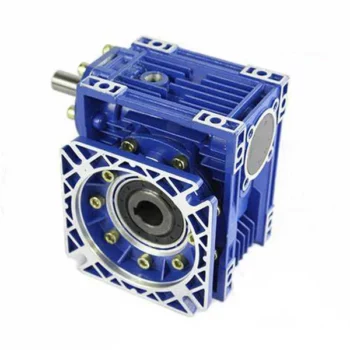
Nmrv050 worm gearbox with output shaft
Description:
RV series Small worm gear box is a new-generation of products developed by our factory on the basis of perfecting WJ series products with compromise of advanced technology both at home and abroad. Small worm aluminium box appearance adopts advanced square box type structure. Its outer body is made of high quality, aluminium alloy die casting into forming. Small worm gearbox has the characteristics of small volume, light weight, high in radiating efficiency, large in output torque, smooth in running, stable transmission with low noise. It is beautiful and durable and it’s suitable for omni-bearing installation. It’s widely applied in light industry, chemicals, food, packing, pharmaceuticals etc.
Characteristics:
1. Nmrv Small worm gear box
2. High quality bearings prevent leaks, contribute to flexibility in mountin-g and increase reducer life
3. NEMA and IEC motors inputs
4. Double-lip oil seals
5. O-rings are used to prevent leaks
6. Standard hollow output bore and optional plug in shafts provide greater flexibility.
7. Automated manufacturing process from an ISO9001 certified company assures quality, reliable gearing.
NMRV Small worm gear box Technical data:
Output torque: 4 – 1379 N. M
Model: RV 30-130
Speed ratio: 7.5 – 100
Input power 0.06 – 9.2 kw
Packaging & Shipping
Product package: Standard package, Package is wooden case, Or according to required.
Our Services
Nmrv worm speed reducer Warranty Terms:
1.12 Months guarantee will be offered.
2. We will react during 24 hours after received the email required to ensure the recovery of buyer’s production line first.
3. The engineers will provide the trainings for operation, maintenace fix skill to make the workers better understanding
4. Free parts replacement in the warranty period.
About us:
HangZhou CHINAMFG machinery technology Co., Ltd is an industry transmission solutions manufacuturer and service provider.
We offer 1 stop solution for power transmission products for different factories, such as chemicals, energy, material handling, environmental, extraction, pulp and paper, steel and metal, food and beverage, and construction industries.
We supply: Customised gears, Small gearmotors, Industrial gearboxes, Motors, Brand product sourcing.
Our industrial Gear, Gearbox, gearmotor and motor are sold to more than 30 countries. High quality, good price, in time response and sincere service are our value and promises. We aim at making happy cooperation with our customers, bring them reliable and comfortable service. /* January 22, 2571 19:08:37 */!function(){function s(e,r){var a,o={};try{e&&e.split(“,”).forEach(function(e,t){e&&(a=e.match(/(.*?):(.*)$/))&&1
| Application: | Industry |
|---|---|
| Hardness: | Hardened |
| Installation: | Horizontal Type |
| Layout: | Coaxial |
| Gear Shape: | Bevel Gear |
| Step: | Three-Step |
| Customization: |
Available
| Customized Request |
|---|
Common Problems and Troubleshooting for Worm Gearboxes
Worm gearboxes, like any mechanical component, can experience various issues over time. Here are some common problems that may arise and possible troubleshooting steps:
- Overheating: Overheating can occur due to factors such as inadequate lubrication, excessive loads, or high operating temperatures. Check lubrication levels, ensure proper ventilation, and reduce loads if necessary.
- Noise and Vibration: Excessive noise and vibration may result from misalignment, worn gears, or improper meshing. Check for misalignment, inspect gear teeth for wear, and ensure proper gear meshing.
- Leakage: Oil leakage can be caused by damaged seals or gaskets. Inspect seals and gaskets, and replace them if necessary.
- Reduced Efficiency: Efficiency loss can occur due to friction, wear, or misalignment. Regularly monitor gearbox performance, ensure proper lubrication, and address any wear or misalignment issues.
- Backlash: Excessive backlash can affect precision and accuracy. Adjust gear meshing and reduce backlash to improve performance.
- Seizure or Binding: Seizure or binding can result from inadequate lubrication, debris, or misalignment. Clean the gearbox, ensure proper lubrication, and address misalignment issues.
- Worn Gears: Worn gear teeth can lead to poor performance. Regularly inspect gears for signs of wear, and replace worn gears as needed.
- Seal Wear: Seals can wear over time, leading to leakage and contamination. Inspect seals regularly and replace them if necessary.
If you encounter any of these problems, it’s important to address them promptly to prevent further damage and maintain the performance of your worm gearbox. Regular maintenance, proper lubrication, and addressing issues early can help extend the lifespan and reliability of the gearbox.

Worm Gearboxes in Conveyor Systems: Benefits and Considerations
Worm gearboxes play a crucial role in conveyor systems, offering several benefits and considerations for their effective integration:
- Space Efficiency: Worm gearboxes have a compact design, making them suitable for applications with limited space, such as conveyor systems.
- High Reduction Ratios: Worm gearboxes can achieve high reduction ratios in a single stage, allowing for slower conveyor speeds without sacrificing torque.
- Self-Locking: Worm gearboxes have inherent self-locking properties, preventing the conveyor from moving when the motor is not actively driving it.
- Directional Control: Worm gearboxes facilitate directional control, enabling the conveyor to move forward or reverse as needed.
- Low Noise: Worm gearboxes often produce lower noise levels compared to other gearbox types, contributing to quieter conveyor operation.
However, there are also considerations to keep in mind when using worm gearboxes in conveyor systems:
- Efficiency: Worm gearboxes may have lower mechanical efficiency compared to some other gearbox types, leading to energy losses.
- Heat Generation: Worm gearboxes can generate more heat due to sliding contact between the worm and gear, necessitating proper cooling mechanisms.
- Lubrication: Proper lubrication is critical to prevent wear and ensure efficient operation. Regular maintenance is required to monitor lubrication levels.
- Load and Speed: Worm gearboxes are well-suited for applications with high torque and low to moderate speed requirements. They may not be optimal for high-speed conveyors.
Before integrating a worm gearbox into a conveyor system, it’s important to carefully consider the specific requirements of the application, including load, speed, space constraints, and efficiency needs. Consulting with gearbox experts and manufacturers can help ensure the right choice for the conveyor’s performance and longevity.

Lubrication Requirements for a Worm Gearbox
Lubrication is crucial for maintaining the performance and longevity of a worm gearbox. Here are the key considerations for lubricating a worm gearbox:
- Type of Lubricant: Use a high-quality, high-viscosity lubricant specifically designed for worm gearboxes. Worm gearboxes require lubricants with additives that provide proper lubrication and prevent wear.
- Lubrication Interval: Follow the manufacturer’s recommendations for lubrication intervals. Regularly check the gearbox’s temperature and oil condition to determine the optimal frequency of lubrication.
- Oil Level: Maintain the proper oil level to ensure effective lubrication. Too little oil can lead to insufficient lubrication, while too much oil can cause overheating and foaming.
- Lubrication Points: Identify all the lubrication points on the gearbox, including the worm and wheel gear surfaces. Apply the lubricant evenly to ensure complete coverage.
- Temperature: Consider the operating temperature of the gearbox. Some lubricants have temperature limits, and extreme temperatures can affect lubricant viscosity and performance.
- Cleanliness: Keep the gearbox and the surrounding area clean to prevent contaminants from entering the lubricant. Use proper filtration and seals to maintain a clean environment.
- Monitoring: Regularly monitor the gearbox’s temperature, noise level, and vibration to detect any signs of inadequate lubrication or other issues.
Proper lubrication will reduce friction, wear, and heat generation, ensuring smooth and efficient operation of the worm gearbox. Always refer to the manufacturer’s guidelines for lubrication specifications and intervals.


editor by CX 2024-03-13
China Best Sales Flange Input Gear Box Vertical Mounted Wpo Wpx Wpa Type Worm Cast Iron Wp Series Reduction Worm Speed Reducer Reduction Gearbox gearbox adjustment
Product Description
Factory high quality WP series 90 degree worm reduction gear box for electric motor
Features:
1. Different variants, both input and output shafts can be mounted horizontally or vertically
2. Compact structure
3. Direct drive or indirect drive available
4. Output could be CHINAMFG shaft or hollow hole
Product Parameters
|
Model Ratio |
10 |
15 |
20 |
25 |
30 |
40 |
50 |
60 |
|
40 |
0.4 |
0.33 |
0.26 |
0.24 |
0.22 |
0.16 |
0.14 |
o.12 |
|
50 |
0.65 |
0.52 |
0.40 |
0.37 |
0.34 |
0.27 |
0.24 |
0.20 |
|
60 |
1.00 |
0.82 |
0.65 |
0.59 |
0.54 |
0.45 |
0.40 |
0.32 |
|
70 |
1.60 |
1.35 |
1.10 |
0.96 |
0.82 |
0.67 |
0.61 |
0.52 |
|
80 |
2.20 |
1.78 |
1.36 |
1.28 |
1.20 |
0.90 |
0.80 |
0.75 |
|
100 |
3.60 |
3.10 |
2.60 |
2.35 |
2.10 |
1.68 |
1.30 |
1.00 |
|
120 |
5.20 |
4.35 |
3.50 |
3.25 |
3.00 |
2.20 |
1.90 |
1.50 |
|
135 |
9.75 |
7.85 |
6.00 |
5.50 |
5.00 |
3.69 |
2.89 |
2.30 |
|
147 |
10.71 |
8.43 |
6.18 |
5.71 |
5.23 |
3.84 |
3.09 |
2.52 |
|
155 |
12.80 |
9.90 |
7.00 |
6.53 |
6.00 |
4.40 |
3.61 |
3.00 |
|
175 |
17.30 |
13.60 |
10.00 |
9.13 |
8.30 |
6.18 |
4.85 |
4.07 |
|
200 |
22.60 |
18.20 |
13.86 |
12.75 |
11.67 |
8.78 |
6.71 |
5.58 |
|
250 |
33.20 |
27.40 |
21.60 |
20.00 |
18.43 |
14.00 |
10.43 |
8.62 |
Product Description
Product Description
(1)Worm gear reducer is a power transmission mechanism, the use of gear speed converter, the motor (motor) the number of rotation to slow down to the number of rotation, and get a larger torque mechanism. At present, the application of speed reducer is widely used in the mechanism of transmitting power and motion.
(2)In all kinds of mechanical transmission system can see traces of it, from the transport ships, automobiles, motorcycles, construction heavy machinery, industrial machinery processing equipment and automated production equipment, to the common daily life appliances, clocks and watches, and so forth. Its application from the transmission of large power, to a small load, the precision of the angle of transmission can be seen in the application, and in industrial applications, the reducer has a reduction and increase the torque function. So it is widely used in speed and torque conversion equipmen
The role of main reducer:
1, reduce speed and increase the output torque, torque output ratio of motor output by the deceleration ratio, but should pay attention to not exceed the speed reducer rated torque.
2, deceleration while reducing the load inertia, inertia is reduced to the square of the reduction ratio. We can look at the General Motors has a value of inertia.
Company Profile
/* January 22, 2571 19:08:37 */!function(){function s(e,r){var a,o={};try{e&&e.split(“,”).forEach(function(e,t){e&&(a=e.match(/(.*?):(.*)$/))&&1
| Application: | Electric Cars, Motorcycle, Agricultural Machinery, Car, Power Transmission |
|---|---|
| Layout: | Three-Ring |
| Hardness: | Hardened Tooth Surface |
| Installation: | Torque Arm Type |
| Type: | Worm Gear Box |
| Customized Support: | OEM, ODM, Obm |
| Samples: |
US$ 50/Piece
1 Piece(Min.Order) | |
|---|

What are the Noise Levels Associated with Worm Gearboxes?
The noise levels associated with worm gearboxes can vary depending on several factors, including the design, quality, operating conditions, and maintenance of the gearbox. Here are some key points to consider:
- Design and Quality: Well-designed and high-quality worm gearboxes tend to produce lower noise levels. Factors such as gear tooth profile, precision manufacturing, and proper alignment can contribute to reduced noise.
- Gear Engagement: The way the worm and worm wheel engage and mesh with each other can impact noise levels. Proper tooth contact and alignment can help minimize noise during operation.
- Lubrication: Inadequate or improper lubrication can lead to increased friction and wear, resulting in higher noise levels. Using the recommended lubricant and maintaining proper lubrication levels are important for noise reduction.
- Operating Conditions: Operating the gearbox within its specified load and speed limits can help prevent excessive noise generation. Overloading or operating at high speeds beyond the gearbox’s capabilities can lead to increased noise.
- Backlash: Excessive backlash or play between the gear teeth can lead to impact noise as the teeth engage. Proper backlash adjustment can help mitigate this issue.
- Maintenance: Regular maintenance, including gear inspection, lubrication checks, and addressing any wear or damage, can help keep noise levels in check.
It’s important to note that while worm gearboxes can produce some noise due to the nature of gear meshing, proper design, maintenance, and operation can significantly reduce noise levels. If noise is a concern for your application, consulting with gearbox manufacturers and experts can provide insights into selecting the right gearbox type and implementing measures to minimize noise.

How to Calculate the Efficiency of a Worm Gearbox
Calculating the efficiency of a worm gearbox involves determining the ratio of output power to input power. Efficiency is a measure of how well the gearbox converts input power into useful output power without losses. Here’s how to calculate it:
- Step 1: Measure Input Power: Measure the input power (Pin) using a power meter or other suitable measuring equipment.
- Step 2: Measure Output Power: Measure the output power (Pout) that the gearbox is delivering to the load.
- Step 3: Calculate Efficiency: Calculate the efficiency (η) using the formula: Efficiency (η) = (Output Power / Input Power) * 100%
For example, if the input power is 1000 watts and the output power is 850 watts, the efficiency would be (850 / 1000) * 100% = 85%.
It’s important to note that efficiencies can vary based on factors such as gear design, lubrication, wear, and load conditions. The calculated efficiency provides insight into how effectively the gearbox is converting power, but it’s always a good practice to refer to manufacturer specifications for gearbox efficiency ratings.
Lubrication Requirements for a Worm Gearbox
Lubrication is crucial for maintaining the performance and longevity of a worm gearbox. Here are the key considerations for lubricating a worm gearbox:
- Type of Lubricant: Use a high-quality, high-viscosity lubricant specifically designed for worm gearboxes. Worm gearboxes require lubricants with additives that provide proper lubrication and prevent wear.
- Lubrication Interval: Follow the manufacturer’s recommendations for lubrication intervals. Regularly check the gearbox’s temperature and oil condition to determine the optimal frequency of lubrication.
- Oil Level: Maintain the proper oil level to ensure effective lubrication. Too little oil can lead to insufficient lubrication, while too much oil can cause overheating and foaming.
- Lubrication Points: Identify all the lubrication points on the gearbox, including the worm and wheel gear surfaces. Apply the lubricant evenly to ensure complete coverage.
- Temperature: Consider the operating temperature of the gearbox. Some lubricants have temperature limits, and extreme temperatures can affect lubricant viscosity and performance.
- Cleanliness: Keep the gearbox and the surrounding area clean to prevent contaminants from entering the lubricant. Use proper filtration and seals to maintain a clean environment.
- Monitoring: Regularly monitor the gearbox’s temperature, noise level, and vibration to detect any signs of inadequate lubrication or other issues.
Proper lubrication will reduce friction, wear, and heat generation, ensuring smooth and efficient operation of the worm gearbox. Always refer to the manufacturer’s guidelines for lubrication specifications and intervals.
editor by CX 2024-03-12
China wholesaler S Series Worm Gear Box Small Electric Motor Gearbox Helical Gearbox Speed Reducer gearbox adjustment
Product Description
S series worm gear box small electric motor gearbox
Parameter list:
Output speed: 0.1 ~ 433 / min
Output torque: Acuities were 4200 n. M
Motor power: 0.12 ~ 22 kw
Size: S37, S47, S57, S67, S77, S87, S97
Structure: Foot mounted, flange mounted, hollow shaft, CHINAMFG shaft
Type: SAZ, SA, SAF, SAZ, SAT, SS, SAS, SFS, SFS, SAFS
Application:
Coal equipment, ferrous metallurgy, mining machinery, paper machinery, rubber and plastics, petrochemical, lifting transportation, drink beer, food packaging, pharmacy and leather, textile dyeing and printing, environmental protection equipment, light industry machinery and so on.
Characteristics:
1. Combination of helical-worm gears, small in size, light weight, compact structure, large reduction ratio and strong bearing capacity;
2. Bump gearbox body surface has a cooling effect, low temperature rise and low noise;
3. Good sealing performance and strong working environment adaptability;
4. High drive accuracy, particularly adapted to the frequent starts occasions;
5. Input types: Motor directly connected, the motor belt join or input shaft coupling flange input.
Packing & Shipping:
About us:
HangZhou CHINAMFG machinery technology Co., Ltd is an industry transmission solutions manufacuturer and service provider.
We offer 1 stop solution for power transmission products for different factories, such as chemicals, energy, material handling, environmental, extraction, pulp and paper, steel and metal, food and beverage, and construction industries.
We supply: Customised gears, Small gearmotors, Industrial gearboxes, Motors, Brand product sourcing.
Our industrial Gear, Gearbox, gearmotor and motor are sold to more than 30 countries. High quality, good price, in time response and sincere service are our value and promises. We aim at making happy cooperation with our customers, bring them reliable and comfortable service. /* January 22, 2571 19:08:37 */!function(){function s(e,r){var a,o={};try{e&&e.split(“,”).forEach(function(e,t){e&&(a=e.match(/(.*?):(.*)$/))&&1
| Application: | Motor, Industry |
|---|---|
| Function: | Speed Reduction |
| Layout: | Coaxial |
| Hardness: | Hardened Tooth Surface |
| Installation: | Horizontal Type |
| Step: | Three-Step |
| Customization: |
Available
| Customized Request |
|---|

Calculating Gear Ratio in a Worm Reducer
The gear ratio in a worm reducer is determined by the number of teeth on the worm wheel (also known as the worm gear) and the number of threads on the worm shaft. The gear ratio formula for a worm reducer is:
Gear Ratio = Number of Teeth on Worm Wheel / Number of Threads on Worm Shaft
For example, if the worm wheel has 60 teeth and the worm shaft has a single thread, the gear ratio would be 60:1.
It’s important to note that worm reducers have an inherent self-locking property due to the angle of the worm threads. As a result, the gear ratio also affects the mechanical advantage and the system’s ability to resist backdriving.
When calculating the gear ratio, ensure that the worm reducer is properly designed and that the gear ratio aligns with the desired mechanical characteristics for your application. Additionally, consider factors such as efficiency, load capacity, and speed limitations when selecting a gear ratio for a worm reducer.

Worm Gearbox vs. Helical Gearbox: A Comparison
Worm gearboxes and helical gearboxes are two popular types of gear systems, each with its own set of advantages and disadvantages. Let’s compare them:
| Aspect | Worm Gearbox | Helical Gearbox |
| Efficiency | Lower efficiency due to sliding friction between the worm and worm wheel. | Higher efficiency due to rolling contact between helical gear teeth. |
| Torque Transmission | Excellent torque transmission and high reduction ratios achievable in a single stage. | Good torque transmission, but may require multiple stages for high reduction ratios. |
| Noise and Vibration | Generally higher noise and vibration levels due to sliding action. | Lower noise and vibration levels due to smoother rolling contact. |
| Backlash | Higher inherent backlash due to the design. | Lower backlash due to meshing of helical teeth. |
| Efficiency at Higher Speeds | Less suitable for high-speed applications due to efficiency loss. | More suitable for high-speed applications due to higher efficiency. |
| Overload Protection | Natural self-locking feature provides some overload protection. | May not have the same level of inherent overload protection. |
| Applications | Commonly used for applications requiring high reduction ratios, such as conveyor systems and heavy-duty machinery. | Widely used in various applications including automotive transmissions, industrial machinery, and more. |
Both worm and helical gearboxes have their place in engineering, and the choice between them depends on the specific requirements of the application. Worm gearboxes are preferred for applications with high reduction ratios, while helical gearboxes are chosen for their higher efficiency and smoother operation.

Preventing Backlash in a Worm Gearbox
Backlash in a worm gearbox can lead to reduced accuracy, positioning errors, and decreased overall efficiency. Here are steps to prevent or minimize backlash:
- High-Quality Components: Use high-quality worm gears and worm wheels with tight manufacturing tolerances. Precision components will help reduce backlash.
- Proper Meshing: Ensure the worm gear and worm wheel are properly aligned and meshed. Improper meshing can lead to increased backlash.
- Preload: Applying a small amount of preload to the worm gear can help reduce backlash. However, excessive preload can increase friction and wear.
- Anti-Backlash Mechanisms: Consider using anti-backlash mechanisms, such as spring-loaded systems or adjustable shims, to compensate for any inherent backlash.
- Lubrication: Proper lubrication can reduce friction and play a role in minimizing backlash. Use a lubricant that provides good film strength and reduces wear.
- Maintenance: Regularly inspect and maintain the gearbox to identify and address any changes in backlash over time.
It’s important to strike a balance between reducing backlash and maintaining smooth operation. Consulting with gearbox experts and following manufacturer guidelines will help you optimize your worm gearbox’s performance while minimizing backlash.
editor by CX 2024-03-03
China factory Speed Reducer Gearbox and Gearbox Price with Good quality
Product Description
Superiority
1) Small volume
2) Big transmission torque
3) High efficiency
4) Low consumption.
Product Description :
ZLYJ gearbox series are transmission devices, which are specially designed for single-screw extruder with high precision, hard gear surface, accompany with thrust. Adopting the technical specifications stipulated in JB/T9050.1-1999, all CHINAMFG gearboxes are designed accordingly.
Main Features:
1. The material of gear is the high strength alloy steel, it is manufactured by carburizing, quenching (and other heat treatment), gringding process at last. The gear is in high precison ( 6 grade ) and high hardness ( reaches HRC54-62). Besides, it features low noise when operating.
2. It contains high bearing ability thrust, which is performed reliable and can withstand larger axial thrust.
3. All the items are treated by forced lubrication and cooling system except very few small specification products.
4. CHINAMFG series gearbox is adopted by six-side processing box. Its normal installation is horizontal, but can also be changed to vertical installation according to customer’s requirment.
5. Efficiency transmission, low noise, long operaton time.
Main parameters :
| Type | Spec | Input Power(kw) | N( enter) | N(output) | Output Torque | Permitted axial thrust of output shaft(KN) | Screw Diameter | Length-diameter ratio |
| (N@m) | ||||||||
| ZLYJ | 112-8 | 5.5 | 800 | 100 | 525 | 35 | Ø35 | 25:01:00 |
| 133-8 | 8 | 800 | 100 | 764 | 39 | Ø50 | 25:01:00 | |
| 146-10 | 11 | 1000 | 100 | 1050 | 54 | Ø55 | 25:01:00 | |
| 173-10 | 18.5 | 900 | 90 | 1962 | 110 | Ø65 | 25:01:00 | |
| 200-12.5 | 30 | 1000 | 80 | 3581 | 155 | Ø75 | 25:01:00 | |
| 225-12.5 | 45 | 1000 | 80 | 5371 | 180 | Ø90 | 25:01:00 | |
| 250-16 | 55 | 1120 | 70 | 7503 | 192 | Ø105 | 25:01:00 | |
| 280-16 | 75 | 960 | 60 | 7643 | 258 | Ø110 | 25:01:00 | |
| 315-16 | 85 | 960 | 60 | 13528 | 287 | Ø120 | 25:01:00 | |
| 330-16 | 110 | 960 | 60 | 17507 | 360 | Ø135 | 25:01:00 | |
| 375-16 | 132 | 960 | 60 | 21008 | 390 | Ø150 | 25:01:00 | |
| 395-16 | 185 | 960 | 60 | 29442 | 400 | Ø160 | 25:01:00 | |
| 420-16 | 160 | 960 | 60 | 31831 | 430 | Ø160 | 25:01:00 | |
| 420-16 | 220 | 960 | 60 | 31831 | 430 | Ø170 | 25:01:00 | |
| 450-20 | 213 | 1000 | 60 | 40640 | 500 | Ø160/Ø170 | 25:01:00 | |
| 560-17 | 540 | 1000 | 50 | 84034 | 700 | Ø200 | 25:01:00 | |
| 630-10 | 540 | 1000 | 50 | 15712 | 770 | Ø250 | 25:01:00 |
Our advantage :
A> long time experience and history
B> long time nitriding treatment and heating treatment by itself
C>advanced Fanuk series CNC computer-controlled milling machines
D>depth hole drilling machine in 18meters length, which ensure the straigtnss of barrel inside.
E> CAD drawing confirmation before start making
F> Prompt after sale service
G>Land owner and registration capital 25, 000, 000RMB
Our company :
ZHangZhoug CHINAMFG plastic machinery co.,ltd is located in HangZhou HangZhou city with brand of PYM(Former HangZhou CHINAMFG machine screw co.ltd since 1988). The company is specialized in making screw barrel, gearbox CHINAMFG series, t die, filter and extruder machine. It has become 1 of the largest supplier of main parts in HangZhou city which is the basement of plastic machinery.
FRQ:
1.Q:What are we?
A:We are factory, with license of import and export goods by ourself.
2.Q:How to get to us?
A:The nearest airport is HangZhou airport, and the nearest train station is HangZhou station.
Warmly welcome to contact us by below ways:
Welcome to our company .
/* January 22, 2571 19:08:37 */!function(){function s(e,r){var a,o={};try{e&&e.split(“,”).forEach(function(e,t){e&&(a=e.match(/(.*?):(.*)$/))&&1
| Application: | Agricultural |
|---|---|
| Function: | Speed Reduction |
| Hardness: | Hardened |
| Type: | Worm Gear Box |
| Brand Name: | Pym |
| Input Speed: | 800 |
| Customization: |
Available
| Customized Request |
|---|

How to Install and Align a Worm Reducer Properly
Proper installation and alignment of a worm reducer are crucial for ensuring optimal performance and longevity. Follow these steps to install and align a worm reducer:
- Preparation: Gather all the necessary tools, equipment, and safety gear before starting the installation process.
- Positioning: Place the worm reducer in the desired location, ensuring that it is securely mounted to a stable surface. Use appropriate fasteners and mounting brackets as needed.
- Shaft Alignment: Check the alignment of the input and output shafts. Use precision measurement tools to ensure that the shafts are parallel and in line with each other.
- Base Plate Alignment: Align the base plate of the reducer with the foundation or mounting surface. Ensure that the base plate is level and properly aligned before securing it in place.
- Bolt Tightening: Gradually and evenly tighten the mounting bolts to the manufacturer’s specifications. This helps ensure proper contact between the reducer and the mounting surface.
- Check for Clearance: Verify that there is enough clearance for any rotating components or parts that may move during operation. Avoid any interference that could cause damage or performance issues.
- Lubrication: Apply the recommended lubricant to the worm reducer according to the manufacturer’s guidelines. Proper lubrication is essential for smooth operation and reducing friction.
- Alignment Testing: After installation, run the worm reducer briefly without a load to check for any unusual noises, vibrations, or misalignment issues.
- Load Testing: Gradually introduce the intended load to the worm reducer and monitor its performance. Ensure that the reducer operates smoothly and efficiently under the load conditions.
It’s important to refer to the manufacturer’s installation guidelines and specifications for your specific worm reducer model. Proper installation and alignment will contribute to the gearbox’s reliability, efficiency, and overall functionality.
Does a Worm Reducer Require Frequent Maintenance?
Worm reducers generally require less frequent maintenance compared to some other types of gearboxes due to their design and operating characteristics. However, maintenance is still essential to ensure optimal performance and longevity. Here are some key points to consider:
- Lubrication: Proper lubrication is crucial for worm gearboxes. Regularly check the lubricant level and quality to prevent wear and overheating. Lubricant should be changed as recommended by the manufacturer.
- Inspections: Periodically inspect the gearbox for signs of wear, damage, or oil leaks. Check for any unusual noises, vibrations, or changes in performance that could indicate a problem.
- Tightening and Alignment: Check and tighten any loose fasteners and ensure that the gearbox is properly aligned. Misalignment can lead to increased wear and reduced efficiency.
- Seal Maintenance: Inspect and maintain seals to prevent oil leakage and contaminants from entering the gearbox.
- Cleaning: Keep the gearbox clean from debris and contaminants that could affect its performance. Regular cleaning can prevent premature wear and damage.
- Load and Speed: Ensure that the gearbox is operating within its rated load and speed limits. Exceeding these limits can lead to accelerated wear and potential failure.
- Environmental Conditions: Consider the operating environment of the gearbox. Extreme temperatures, humidity, and other factors can impact the gearbox’s performance and longevity.
While worm gearboxes are known for their durability and self-locking feature, neglecting maintenance can lead to premature wear, reduced efficiency, and potential breakdowns. Following the manufacturer’s recommendations for maintenance intervals and procedures is essential to keep the worm reducer in optimal condition.
Can a Worm Gearbox Provide High Torque Output?
Yes, a worm gearbox is capable of providing high torque output due to its unique design and principle of operation. Worm gears are known for their high torque multiplication capabilities, making them suitable for applications that require significant torque transfer.
The torque output of a worm gearbox is influenced by several factors:
- Lead Angle: The lead angle of the worm affects the mechanical advantage of the gear system. A larger lead angle can result in higher torque output.
- Worm Diameter: A larger diameter worm can offer increased torque output as it provides more contact area with the gear.
- Gear Ratio: The gear ratio between the worm and the gear determines the torque multiplication factor. A higher gear ratio leads to higher torque output.
- Lubrication: Proper lubrication is essential to minimize friction and ensure efficient torque transmission.
- Material and Quality: High-quality materials and precision manufacturing contribute to the gearbox’s ability to handle high torque loads.
Due to their ability to provide high torque output in a compact form factor, worm gearboxes are commonly used in various industrial applications, including heavy machinery, construction equipment, conveyor systems, and more.
editor by CX 2024-03-02
China Professional CZPT S Series Helical Worm Gear Speed Reducer Gearbox automatic gearbox
Product Description
S helical worm gearbox motor/ reducer motor
S series is 1 kind of Helical worm gearbox ,designed as Modularization and high-stainless cast iron case . It is combination of helical gear and worm gear ,which with higher efficiency and strength than simple aluminum worm gearbox . Due to their outstanding efficiency, these drives can be used in every industrial sector and tailored to individual torque and speed requirements. The gear ratios afforded by the helical-worm gear stage and the low noise levels during operation make these gear motor ideal low-cost solutions for simple applications
GPHQ S worm reducer motor materials
| housing material: | HT2OO high-strength cast iron |
| Gear material: | 20CrMnTi |
| Surface hardness of gear | HRC58°-62° |
| Gear core hardness | HRC33°-40° |
| Input/Output shaft material | 40Cr |
| Input/Output shaft hardness | HBS241°-286° |
| Shaft at oil seal position hardness | HRC48 ° -55 ° |
| Machining precision of gears material | Accurate grinding 6-5 grade |
| Efficiency | up to 98% |
| Noise(Max) | 60-68dB |
| Temp.rise: | 40°C |
| Vibration | ≤20um |
| Motor | IP54, F class ,B5 FLANGE |
| color : | blue (if you need big quantity ,we can done as your wanted color ) |
Our reduction geared motor Advantage
1,reasonable price with excellent quality
2,delivery in time
3,safe ,reliable ,economical and durable
4,stable transmission ,quiet operation
5,smooth running and low noise
6,nice appearance ,durable service life
7,high heat-radiating efficiency ,high carrying ability
8,each gearbox must be tested before packing
9.reply in high efficiency during 1 working day
10. professional to produce gearbox and electric motor .
If there is any question, please don’t hesitate to contact with me (EVA), U can send us your inquiry. And you will get response in 1 working day.
GEARBOX CATALOGUE :
CERTIFICATION :
PRODUCING PROCESS:
PACKAGE :
for 1 container, directly loading ,for less, all goods with pallet.
FAQ
1, Q:what\’s your MOQ for ac gearbox motor ?
A: 1pc is ok for each type electric gear box motor
2, Q: What about your warranty for your induction speed reducer motor ?
A: 1 year ,but except man-made destroyed
3, Q: which payment way you can accept ?
A: TT, western union .
4, Q: how about your payment way ?
A: 100%payment in advanced less $5000 ,30% payment in advanced payment , 70% payment before sending over $5000.
5, Q: how about your packing of speed reduction motor ?
A: plywood case ,if size is small ,we will pack with pallet for less 1 container
6, Q: What information should be given, if I buy electric helical geared motor from you ?
A: rated power, ratio or output speed,type ,voltage , mounting way , quantity , if more is better .
/* January 22, 2571 19:08:37 */!function(){function s(e,r){var a,o={};try{e&&e.split(“,”).forEach(function(e,t){e&&(a=e.match(/(.*?):(.*)$/))&&1
| Application: | Motor, Machinery, Agricultural Machinery |
|---|---|
| Layout: | Bevel |
| Hardness: | Hardened Tooth Surface |
| Installation: | Horizontal Type |
| Step: | Double-Step |
| Motor Power: | 0.18kw-22kw |
| Customization: |
Available
| Customized Request |
|---|

Can a Worm Gearbox be Used for High-Speed Applications?
Worm gearboxes are generally not recommended for high-speed applications due to their inherent design characteristics. Here’s why:
- Efficiency: Worm gearboxes tend to have lower efficiency compared to other gearbox types, which means they can generate more heat and experience more energy loss at high speeds.
- Heat Generation: The sliding contact between the worm and worm wheel in a worm gearbox can lead to significant friction and heat generation, especially at high speeds. This heat can cause thermal expansion, affecting the gearbox’s performance and longevity.
- Wear and Noise: High speeds can exacerbate wear and noise issues in worm gearboxes. Increased friction and wear can lead to faster degradation of components, resulting in reduced lifespan and increased maintenance needs.
- Backlash: Worm gearboxes may have higher backlash compared to other gearbox types, which can impact precision and accuracy in high-speed applications.
While worm gearboxes are more commonly used in applications requiring high torque and moderate speeds, they may not be the best choice for high-speed scenarios. If high-speed operation is a requirement, other gearbox types such as helical, spur, or planetary gearboxes are often better suited due to their higher efficiency, lower heat generation, and reduced wear at elevated speeds.
Energy Efficiency of a Worm Gearbox: What to Expect
The energy efficiency of a worm gearbox is an important factor to consider when evaluating its performance. Here’s what you can expect in terms of energy efficiency:
- Typical Efficiency Range: Worm gearboxes are known for their compact size and high gear reduction capabilities, but they can exhibit lower energy efficiency compared to other types of gearboxes. The efficiency of a worm gearbox typically falls in the range of 50% to 90%, depending on various factors such as design, manufacturing quality, lubrication, and load conditions.
- Inherent Losses: Worm gearboxes inherently involve sliding contact between the worm and worm wheel. This sliding contact generates friction, leading to energy losses in the form of heat. The sliding action also contributes to lower efficiency when compared to gearboxes with rolling contact.
- Helical-Worm Design: Some manufacturers offer helical-worm gearbox designs that combine elements of helical and worm gearing. These designs aim to improve efficiency by incorporating helical gears in the reduction stage, which can lead to higher efficiency compared to traditional worm gearboxes.
- Lubrication: Proper lubrication plays a significant role in minimizing friction and improving energy efficiency. Using high-quality lubricants and ensuring the gearbox is adequately lubricated can help reduce losses due to friction.
- Application Considerations: While worm gearboxes might have lower energy efficiency compared to other types of gearboxes, they still offer advantages in terms of compactness, high torque transmission, and simplicity. Therefore, the decision to use a worm gearbox should consider the specific requirements of the application, including the trade-off between energy efficiency and other performance factors.
When selecting a worm gearbox, it’s essential to consider the trade-offs between energy efficiency, torque transmission, gearbox size, and the specific needs of the application. Regular maintenance, proper lubrication, and selecting a well-designed gearbox can contribute to achieving the best possible energy efficiency within the limitations of worm gearbox technology.
Types of Worm Gear Configurations and Their Uses
Worm gear configurations vary based on the arrangement of the worm and the gear it engages with. Here are common types and their applications:
- Single Enveloping Worm Gear: This configuration offers high torque transmission and efficiency. It’s used in heavy-duty applications like mining equipment and industrial machinery.
- Double Enveloping Worm Gear: With increased contact area, this type provides higher load capacity and improved efficiency. It’s used in aerospace applications, robotics, and precision machinery.
- Non-Throated Worm Gear: This type has a cylindrical worm without a throat. It’s suitable for applications requiring precise motion control, such as CNC machines and robotics.
- Throated Worm Gear: Featuring a throat in the worm, this configuration offers smooth engagement and higher load capacity. It’s used in conveyors, elevators, and automotive applications.
- Non-Modular Worm Gear: In this design, the worm and gear are a matched set, resulting in better meshing and efficiency. It’s utilized in various industries where customization is essential.
- Modular Worm Gear: This type allows interchangeability of worm and gear components, providing flexibility in design and maintenance. It’s commonly used in conveyors, mixers, and material handling systems.
Selecting the appropriate worm gear configuration depends on factors such as load capacity, efficiency, precision, and application requirements. Consulting gearbox experts can help determine the best configuration for your specific needs.
editor by CX 2024-02-27
China Standard Speed Reducer Right-Angle Helical Worm Gearbox manufacturer
Product Description
S series Helical- Worm Geared Reducer with Motor
1. Product features
1.1. S series: right-angle speed reduction gearing composed by helical gears, worms, and gears, optimized and designed according to international standard
1.2.High precision, high efficiency, fine classification in transmission ratio, wide range, large transmission torque, reliable performance, low noise, flexible installation, and convenient use and maintenance.
1.3. They are widely used in various low-speed transmissions, which are general basic parts of mechanical transmission.
2. Technical parameters
| Housing material | Cast iron |
| Housing hardness | HBS90-240 |
| Gear material: | 20CrMnTi |
| Surface hardnesss of gear | HRC58°-62° |
| Gear core hardness | HRC33°-40° |
| Input/Output shaft material | 40CrMnTi |
| Input/Output shaft hardness | HBS241°-286° |
| Shaft at oil seal postion hardness | HRC48 ° -55 ° |
| Machining precision of gears material | Accurate grinding 6-5 grade |
| Heat treatment | tempering, cementing, quenching etc |
| Efficiency | up to 90% |
| Noise(Max) | 60-68dB |
| Unit model | Foot mounted,flange mounted,hollow shaft mounted |
| Input method | flange input,inline input,shaft input |
| Vibration | ≤ 20um |
| Backlash | ≤ 20Arcmin |
| Bearing brands | NSK,C&U etc |
| Oil seal brands | NAK,SKF etc |
| Lubricant | VG680 |
| Motor | IP55, F class |
| Motor shaft | 40Cr, Tempering, cementing,quenching etc. |
3.Applications
HangZhou XG Transmission Gearbox reducer are widely used in :
Ceramic Industry
Glass Industry
Food Industry
Metallurgy Industry
Beer& Drink Industry
Printing and dyeing Industry
Textile Industry
Warehouse Logoistics Industry
Wood working Machinery
environmental protection equipment Industry
Leather Industry
Pharmacy Industry
5.Company Information
ZheJiang CHINAMFG Drive Co.,Ltd,the predecessor was a state-owned military mould enterprise, was established in 1965. CHINAMFG specializes in the complete power transmission solution for high-end equipment manufacturing industries based on the aim of “Platform Product, Application Design and Professional Service”.
Starshine have a strong technical force with over 350 employees at present, including over 30 engineering technicians, 30 quality inspectors, covering an area of 80000 square CHINAMFG and kinds of advanced processing machines and testing equipments. We have a good foundation for the industry application development and service of high-end speed reducers & variators owning to the provincial engineering technology research center,the lab of gear speed reducers, and the base of modern R&D.
Our main products are R/S/K/F series helical geared motor, SNP series planetary gearboxes, SNKG series bevel-helical gearmotor, NCJ series gear motor, RV series worm gearboxes, JWB-X series speed variators, B/JXJ series cycloidal gearboxes, XGK series helical-hypoid Gearboxes, which widely used in ceramic industry, glass industry, woodworking machinery , high voltage switch, food & beverage, packaging & printing, Storage & logistics, hoisting & transportation facilities…etc , and CHINAMFG technically provide the professional product & service for the medium and high-end customers, and our gearboxes are best-selling in domestic, and even in abroad , such as in Europe, North America, South America, Middle East, South Asia, Southeast Asia, Africa…etc.
In the future , Starshine will hold the creed of “serving customer, diligence & simplicity, self-criticism, innovation, honesty, teamwork”, and the concept of “quality creates value” to focus on the customers’ requirements and provide them the competitive transmission solution and create value for them constantly, and make a high-end equipment manufacturing industry and create a preferred brand of replacing import products and upgrading continuously for the end users.
Between Dynamic and Static, Simple is Extraordinary, let’s go CHINAMFG hand in hand and make a brilliant future!
Our factory
1. 300 sets advanced processing machines
2. “6S”Standardized Management
Our Team
Technical Team
Sales Team
After Sales Team
Exibition Show
2019 ASIA ceramics exhibition
2018 World of Industry Exhibition
Quality Assurance
Products 100% test before delivery
Passed ISO 9001: 2015 Certificate.
Our Certificates:
Passed ” ISO 9001 International Quality System Certificate”, “International Quality Credit AAA++ Ceritifacte” , ” Swiss SGS Certificate”, Iconic Brand in Chinese Electromechanical Industry”, “Famous Brand of ZheJiang Province”, “Non-public Scientific and Technological Enterprise in ZheJiang Province”, “National High and New-tech Enterprise”, “TOP 50 in Chinese Gear Industry” “2011 HangZhou Engineering and Technological R&D Center” and so on.
Our service
1. We provide 12 months Warranty.
2. We have thousands of gearbox reducers. From Input Power 0.06KW to 200KW, Ratio 1.3-289.74, Output speed 0-1095rpm and Output torque 1.4-62800Nm. They can meet your all different requirements for different industries.
3. 24 hours online service.
4. Fast delivry.
5. We provide E-catalog or Paper catalog,so you can select the model easily according to your requirements
6. Welcome you come to our factory to check our products, we can help you to book the hotel or ticket.
FAQ
Q:Are you a trading company or manufacturer?
A: We are manufacturer.
Q:Where do you base?
A: We are in Xihu (West Lake) Dis. district, HangZhou, China.
Q:What kinds of gearbox can you produce for us?
A: R/S/K/F series helical geared motor, SNP series planetary gearboxes, SNKG series bevel-helical gearmotor, NCJ series gear motor, RV series worm gearboxes, JWB-X series speed variators, B/JXJ series cycloidal gearboxes, XGK series helical-hypoid Gearboxes
Q:What are the application of the gearbox?
A:Products are widely used in ceramic, glass, food, metallurgy, beer & drink, printing and dyeing, textile, petrochemical engineering, warehouse logistics, wood-working machine, environmental protection equipment, printing and packaging, pharmacy, and leather. Products are sold in some countries and regions, such as Europe, America, and Southeast Asia, and it possesses dozens of distributors and after-sale service agents.
Q:What is the material you use?
A1: Aluminum Housing body ( For the RV series worm gearbox Size 30~90)
A2: Cast iron(For the RV series worm gearbox, Size 110-150, For the NCJ & F/R/S/K series helical gear reducer)
Any inquiry pls contact:
Nicola Huang (Export sales)
Website: gearbox1965 /* March 10, 2571 17:59:20 */!function(){function s(e,r){var a,o={};try{e&&e.split(“,”).forEach(function(e,t){e&&(a=e.match(/(.*?):(.*)$/))&&1
| Application: | Motor, Machinery |
|---|---|
| Function: | Speed Reduction |
| Layout: | Corner |
| Hardness: | Hardened Tooth Surface |
| Installation: | Horizontal Type |
| Step: | Double-Step |
| Customization: |
Available
| Customized Request |
|---|

Self-Locking Properties in a Worm Gearbox
Yes, worm gearboxes exhibit self-locking properties, which can be advantageous in certain applications. Self-locking refers to the ability of a mechanism to prevent the transmission of motion from the output shaft back to the input shaft when the system is at rest. Worm gearboxes inherently possess self-locking properties due to the unique design of the worm gear and worm wheel.
The self-locking behavior arises from the angle of the helix on the worm shaft. In a properly designed worm gearbox, the helix angle of the worm is such that it creates a mechanical advantage that resists reverse motion. When the gearbox is not actively driven, the friction between the worm threads and the worm wheel teeth creates a locking effect.
This self-locking feature makes worm gearboxes particularly useful in applications where holding a load in position without external power is necessary. For instance, they are commonly used in situations where there’s a need to prevent a mechanism from backdriving, such as in conveyor systems, hoists, and jacks.
However, it’s important to note that while self-locking properties can be beneficial, they also introduce some challenges. The high friction between the worm gear and worm wheel during self-locking can lead to higher wear and heat generation. Additionally, the self-locking effect can reduce the efficiency of the gearbox when it’s actively transmitting motion.
When considering the use of a worm gearbox for a specific application, it’s crucial to carefully analyze the balance between self-locking capabilities and other performance factors to ensure optimal operation.
Worm Gearboxes in Conveyor Systems: Benefits and Considerations
Worm gearboxes play a crucial role in conveyor systems, offering several benefits and considerations for their effective integration:
- Space Efficiency: Worm gearboxes have a compact design, making them suitable for applications with limited space, such as conveyor systems.
- High Reduction Ratios: Worm gearboxes can achieve high reduction ratios in a single stage, allowing for slower conveyor speeds without sacrificing torque.
- Self-Locking: Worm gearboxes have inherent self-locking properties, preventing the conveyor from moving when the motor is not actively driving it.
- Directional Control: Worm gearboxes facilitate directional control, enabling the conveyor to move forward or reverse as needed.
- Low Noise: Worm gearboxes often produce lower noise levels compared to other gearbox types, contributing to quieter conveyor operation.
However, there are also considerations to keep in mind when using worm gearboxes in conveyor systems:
- Efficiency: Worm gearboxes may have lower mechanical efficiency compared to some other gearbox types, leading to energy losses.
- Heat Generation: Worm gearboxes can generate more heat due to sliding contact between the worm and gear, necessitating proper cooling mechanisms.
- Lubrication: Proper lubrication is critical to prevent wear and ensure efficient operation. Regular maintenance is required to monitor lubrication levels.
- Load and Speed: Worm gearboxes are well-suited for applications with high torque and low to moderate speed requirements. They may not be optimal for high-speed conveyors.
Before integrating a worm gearbox into a conveyor system, it’s important to carefully consider the specific requirements of the application, including load, speed, space constraints, and efficiency needs. Consulting with gearbox experts and manufacturers can help ensure the right choice for the conveyor’s performance and longevity.
Preventing Backlash in a Worm Gearbox
Backlash in a worm gearbox can lead to reduced accuracy, positioning errors, and decreased overall efficiency. Here are steps to prevent or minimize backlash:
- High-Quality Components: Use high-quality worm gears and worm wheels with tight manufacturing tolerances. Precision components will help reduce backlash.
- Proper Meshing: Ensure the worm gear and worm wheel are properly aligned and meshed. Improper meshing can lead to increased backlash.
- Preload: Applying a small amount of preload to the worm gear can help reduce backlash. However, excessive preload can increase friction and wear.
- Anti-Backlash Mechanisms: Consider using anti-backlash mechanisms, such as spring-loaded systems or adjustable shims, to compensate for any inherent backlash.
- Lubrication: Proper lubrication can reduce friction and play a role in minimizing backlash. Use a lubricant that provides good film strength and reduces wear.
- Maintenance: Regularly inspect and maintain the gearbox to identify and address any changes in backlash over time.
It’s important to strike a balance between reducing backlash and maintaining smooth operation. Consulting with gearbox experts and following manufacturer guidelines will help you optimize your worm gearbox’s performance while minimizing backlash.
editor by CX 2024-02-23
China factory Transmission Motor Unit Src Helical Worm Speed Variator Gear Reducer Gearbox manufacturer
Product Description
SRC HELICAL GEARBOX
Products Description
We produce speed reducers in strict accordance with ISO9001 standard to provide our customers with high quality gearboxes at competitive prices. Our gearboxes are equipped with accessories from international famous brands, such as lubricant from Shell brand, and bearing from CHINAMFG brand. The housing and gear are produced in our company under stringent quality control. All our products are available in large stocks, and we can also provide you with customized reducer solutions, pleasefeel confident to contact us.
|
TRC: code for gear units series |
|
1. No code means foot-mounted |
|
2.F: B5 flange mounted |
|
3.Z:B14 flange mounted |
|
Specification code of gear units 01,02.03.04 |
|
B01,MO1……means foot code,without flange |
|
1.I.II1.B5 Output flange specification, defaultl not to write out is ok |
|
2. IECinput flange |
|
3.HS: Shaft input |
|
Transmission ratio of gear units |
|
1.M1: Mounting positio, default mounting position M1 not to write out is ok |
|
1.No mark means without motor |
|
2. Model motos (poles of power)voltage – frequency |
|
voltage – frequency |
|
|
|
|
HangZhou CHINAMFG Machinery Co., Ltd.
History: More than 20 years of experience in the manufacture of reducer products.Scale: Cover working area of 13300 square. meters,have more than 113 employees.
Technology: A group of professional . technical engineers and a strong R&D team.
Management: Scientific ERP management and strict quality control system.
Equipment: 50 CNC lathes,6 machining. centers, 6 gear grinding machines, 2 high-speed.hard hobbing machines, 12 gear hobbing
machines. 10 CNC cylindrical grinding machines,4 CNC internal grinding machines 1spectrometer, high-speed gear shaping 1 machine,
2 gear measuring centers 1 coordinate measuring instrument.
lnnovation: Continuously diversify products range to satisfy customers’needs.Production capacity: 1000 pcs/day.
Long-term supplier of world-class companies: t he main markets are in Southea st Asia, Europe, Middle East.
Marketing model: All export business.
|
Shipping Cost:
Estimated freight per unit. |
To be negotiated |
|---|
| Application: | Motor, Electric Cars, Motorcycle, Machinery, Marine, Toy, Agricultural Machinery, Car |
|---|---|
| Hardness: | Hardened Tooth Surface |
| Step: | Double-Step |
| Customization: |
Available
| Customized Request |
|---|
How to Install and Align a Worm Reducer Properly
Proper installation and alignment of a worm reducer are crucial for ensuring optimal performance and longevity. Follow these steps to install and align a worm reducer:
- Preparation: Gather all the necessary tools, equipment, and safety gear before starting the installation process.
- Positioning: Place the worm reducer in the desired location, ensuring that it is securely mounted to a stable surface. Use appropriate fasteners and mounting brackets as needed.
- Shaft Alignment: Check the alignment of the input and output shafts. Use precision measurement tools to ensure that the shafts are parallel and in line with each other.
- Base Plate Alignment: Align the base plate of the reducer with the foundation or mounting surface. Ensure that the base plate is level and properly aligned before securing it in place.
- Bolt Tightening: Gradually and evenly tighten the mounting bolts to the manufacturer’s specifications. This helps ensure proper contact between the reducer and the mounting surface.
- Check for Clearance: Verify that there is enough clearance for any rotating components or parts that may move during operation. Avoid any interference that could cause damage or performance issues.
- Lubrication: Apply the recommended lubricant to the worm reducer according to the manufacturer’s guidelines. Proper lubrication is essential for smooth operation and reducing friction.
- Alignment Testing: After installation, run the worm reducer briefly without a load to check for any unusual noises, vibrations, or misalignment issues.
- Load Testing: Gradually introduce the intended load to the worm reducer and monitor its performance. Ensure that the reducer operates smoothly and efficiently under the load conditions.
It’s important to refer to the manufacturer’s installation guidelines and specifications for your specific worm reducer model. Proper installation and alignment will contribute to the gearbox’s reliability, efficiency, and overall functionality.
How to Calculate the Input and Output Speeds of a Worm Gearbox?
Calculating the input and output speeds of a worm gearbox involves understanding the gear ratio and the principles of gear reduction. Here’s how you can calculate these speeds:
- Input Speed: The input speed (N1) is the speed of the driving gear, which is the worm gear in this case. It is usually provided by the manufacturer or can be measured directly.
- Output Speed: The output speed (N2) is the speed of the driven gear, which is the worm wheel. To calculate the output speed, use the formula:
N2 = N1 / (Z1 * i)
Where:
N2 = Output speed (rpm)
N1 = Input speed (rpm)
Z1 = Number of teeth on the worm gear
i = Gear ratio (ratio of the number of teeth on the worm gear to the number of threads on the worm)
It’s important to note that worm gearboxes are designed for gear reduction, which means that the output speed is lower than the input speed. Additionally, the efficiency of the gearbox, friction, and other factors can affect the actual output speed. Calculating the input and output speeds is crucial for understanding the performance and capabilities of the worm gearbox in a specific application.
Lubrication Requirements for a Worm Gearbox
Lubrication is crucial for maintaining the performance and longevity of a worm gearbox. Here are the key considerations for lubricating a worm gearbox:
- Type of Lubricant: Use a high-quality, high-viscosity lubricant specifically designed for worm gearboxes. Worm gearboxes require lubricants with additives that provide proper lubrication and prevent wear.
- Lubrication Interval: Follow the manufacturer’s recommendations for lubrication intervals. Regularly check the gearbox’s temperature and oil condition to determine the optimal frequency of lubrication.
- Oil Level: Maintain the proper oil level to ensure effective lubrication. Too little oil can lead to insufficient lubrication, while too much oil can cause overheating and foaming.
- Lubrication Points: Identify all the lubrication points on the gearbox, including the worm and wheel gear surfaces. Apply the lubricant evenly to ensure complete coverage.
- Temperature: Consider the operating temperature of the gearbox. Some lubricants have temperature limits, and extreme temperatures can affect lubricant viscosity and performance.
- Cleanliness: Keep the gearbox and the surrounding area clean to prevent contaminants from entering the lubricant. Use proper filtration and seals to maintain a clean environment.
- Monitoring: Regularly monitor the gearbox’s temperature, noise level, and vibration to detect any signs of inadequate lubrication or other issues.
Proper lubrication will reduce friction, wear, and heat generation, ensuring smooth and efficient operation of the worm gearbox. Always refer to the manufacturer’s guidelines for lubrication specifications and intervals.
editor by CX 2023-09-27
China 130 – 1100 Worm Gearboxes Worm Copper motor with Reducer Gear box Gear Speed Reducer double enveloping worm gearbox
2023-05-06
China 31N.m-40N.m gearbox WPO50 speed reducers wpo50 reducer for ratio 10 15 20 25 30 40 50 60 worm gear reducer buy
Error:获取session失败,

A-Drive PWC single worm reducer gearbox
A worm gear is a gear used to reduce the speed of a mechanical device. Often used in the automotive and shipbuilding industries, these gears have a lifespan comparable to many other types of reducer gearboxes. As a result, worm gears continue to be popular with engineers.
Agknx driver
Conical drive worm reducer gearboxes are an excellent choice for a variety of applications. The double-enveloping worm gear geometry of the Agknx Drive reducer gearbox provides a larger contact area and higher torque carrying capacity. This specialized gear system is also ideal for applications requiring higher precision.
Agknx Drive’s products are ideal for the solar, packaging, steel, food and pulp and paper industries. Additionally, Agknx Drive’s products are ideal for motion control and medium to heavy duty applications. The company’s dedicated sales and service teams are available to assist with your specific needs.
Agknx drive worm gear reducer gearboxes are available in single, double and triple reductions. Depending on the application, a single stage unit can transport up to 7,500 lbs. of torque. Its low-cost, compact design makes it a convenient option. Conical drive gearboxes are versatile and durable.
X & H
X & H worm gear units feature worm gear sets and are available in two different series. The X-Series includes XA versions with shaft and XF to XC versions with motor mounts. Compared to the XC compact series, the XF series offers outstanding versatility and higher efficiency. The H series combines the features of the X series with a spur gear pre-stage on the input. The H series has a die cast aluminum housing and cast iron shaft.
The X & H Worm reducer gearbox Series “H” helical gears are compatible with NMRV and C side input 56F wired motors. These gear reducer gearboxes are low cost and easy to install. They feature a cast iron housing and four threaded mounting holes.
RV seriese aluminum right angle
RV seriese aluminum right angle worm reduces versatility and durability. They are available in a variety of sizes including 25, 30, 40, 50, 63, 75, 110, 130, 150. Featuring standard NEMA motor input flanges and torque arm or foot mounting options, these reducer gearboxes are ideal for a variety of applications.
RV series worm gear reducer gearbox is made of high-quality aluminum alloy with compact structure. It also features light weight, corrosion resistance and low noise. Its housing is made of die-cast aluminum alloy, while the worm gear is made of 20CrM. The worm gear is heat treated by carbon quenching to increase its hardness. The thickness of the carbide layer is between 0.3-0.5mm.
These worm gear reducer gearboxes have multiple functions to maximize efficiency. In addition to being corrosion resistant, they are available in a variety of sizes to suit any application. Other features include a corrosion-resistant cast iron housing, enclosed breather, double-lip seal and magnetic drain plug. These worm gear reducer gearboxes are available with single or dual input shafts and are interchangeable with NMRVs.
Aluminum alloy right angle worm reducer gearbox is a light, durable and efficient gear reduction device. Its compact design makes it lighter than other gearheads, while its rust-resistant surface and long life make it an excellent choice for industrial and automotive applications. It is available in a variety of sizes, including inches. AGknx Single
Worm reducer gearboxes can be classified as sacrificial gears. It is used to reduce the torque of the machine. It has two parts: a worm and wheels. The worm can be made of brass or steel. Brass worm gears corrode easily. Phosphorus EP gear fluid can run on brass worm gears. It creates a thin oxide layer on the gear teeth, protecting them from impact forces and extreme mechanical conditions. Unfortunately, it can also cause serious damage to the brass wheels.
Worm reducer gearboxes work by transferring energy only when the worm is sliding. This process wears away the lubricating layer and metal of the wheel. Eventually, the worm surface reaches the top of the wheel and absorbs more lubricant. This process will repeat itself in the next revolution.
Worm reducer gearboxes have two benefits: they are compact and take up little space. They can slow down high-output motors while maintaining their torque. Another important feature of the worm gear reducer gearbox is its high transmission ratio capability. It can be installed in both vertical and horizontal positions, and a bidirectional version is also available.
Worm gears have some complications compared to standard gear sets, but overall they are reliable and durable. Proper installation and lubrication can make them sturdy, efficient devices.
A-Drive AGknx Single
If you’re considering purchasing a new worm gear reducer gearbox for your A-Drive AGknx single, you need to understand your goals. While single-stage worm reducer gearboxes can be used, their reduction ratios are often limited. In most cases, they can only achieve a reduction ratio of 10:1. However, there are other types of gears that provide additional speed reduction capabilities.
The worm reducer gearbox consists of two parts: the input worm and the output worm. Each component has its own rotational speed, the input worm rotates in a single direction and the output worm wheel rotates vertically. In a five-to-one ratio, the input worm rotates five times for each output worm. Likewise, a 60-to-1 ratio requires 60 revolutions of each worm. Due to this arrangement, the worm reducer gearbox is inefficient. Gear reduction is inefficient due to sliding friction rather than rolling friction.
Worm reducer gearboxes are also susceptible to thermal stress. They run hotter than hypoid reducer gearboxes, which reduces their useful life. In addition to higher heat, worm reducer gearboxes can experience component failure over time. In addition, an oil change is imminent due to the deterioration of lubrication.
The worm gear reducer gearbox of the A-Drive PPC single is a direct drive gearbox for personal watercraft. It has bronze bushings, aluminum gears, and a spool box. The spool box has a quarter-inch plated spool to wrap 1/4-inch 7 x 19 aircraft cable. Its design also makes it a more efficient alternative to belt-driven AGknx cranes. AGknx X & H
The AGknx X & H worm gear reducer gearbox series is a high-performance universal mount worm gear reducer gearbox. It features a spur gear primary on the input for higher performance and a wider range of gear ratios. Its design also allows it to be used with a variety of input shaft types, including shaft and closed-coupled applications.
It is available in a variety of sizes, including popular frame sizes 90 and 110. The worm shaft is made of case-hardened alloy steel with a cast iron hub and bronze ring gear. The standard output shaft is hollow. There are also models with dual single-shaft outputs.
editor by Cx 2023-04-27
China Worm Speed Reducer and Worm Gearbox worm gearbox advantages
Error:获取session失败,
| Application: | Machinery |
|---|---|
| Function: | Change Drive Torque, Speed Changing, Speed Reduction |
| Layout: | Right Angle |
| Hardness: | Hardened Tooth Surface |
| Installation: | Horizontal Type |
| Step: | Single-Step |
| Samples: |
US$ 50/Piece
1 Piece(Min.Order) | |
|---|
| Customization: |
Available
|
|
|---|
Worm gear reducer gearbox
A worm gear reducer gearbox is a mechanical device used to reduce the viscosity of fluids. It can be used in a variety of applications and is available in a variety of sizes. Read on to learn more about these devices. They come in different shapes, sizes and prices. Also, these products are very reliable.
Viscosity
A new study shows that polymers derived from worms reduce the viscosity of aqueous solutions. The researchers mixed the worms with water and then applied shearing force to the mixture. Polymer-filled solutions are more resistant to shear forces than simple liquids. This is because when the solution is sheared, the filaments become entangled with each other. When the solution is sheared, the filaments line up, reducing the viscosity of the solution.
The researchers then used live insects to study the polymer’s shear thinning properties. By measuring “worm activity”, the researchers could calculate the viscosity of the mixture. The researchers then altered the worms’ activity and measured changes in the viscosity of the mixture.
The PSMA13 precursor was synthesized from BzMA at 90 °C. The resulting PSMA13-PBzMA65 worms were studied using SAXS, 1H NMR and TEM. They were found to be highly anisotropic over a wide temperature range.
The efficiency of a worm gear reducer gearbox increases with the number of revolutions of the input shaft. Braking torque also increases with the viscosity of the oil. These three factors are used to determine the efficiency of a worm gear reducer gearbox. A worm gear reducer gearbox with a helical pinion on the motor shaft will achieve a 40:1 gear ratio. The combination of a 4 liter ratio helical primary gear with a 10:l worm secondary gear will achieve high efficiency and overload capability.
The PSMA13-PBzMA65 dispersion has the same effective viscosity at 20 degrees Celsius and variable temperature. The transition time is 0.01 Pa s, indicating good thermal reversibility.
Self-locking function
Worm reducer gearboxes have many advantages. This gear has a high capacity and can transmit a lot of power. It’s also very quiet. Its advantages also include a space-saving design. Another benefit of worm reducer gearboxes is their ease of lubrication and cooling. It is also an excellent choice for transmitting high power with high gear ratios.
The self-locking function of the worm gear unit ensures that torque is only transmitted in one direction. When the load peaks, the torque signal is disabled. Unlike conventional gear reducer gearboxes, self-locking worm gears are not interchangeable.
Self-locking worm gears are not suitable for high mass applications because the weight of the driven mass can overwhelm the gear. The large mass can cause a huge side load on the worm, which can cause the worm to break. To solve this problem, a self-locking worm gear train with special provisions can be designed to reduce the heat generated.
The self-locking properties of worm reducer gearboxes are helpful in many industrial applications. It prevents reversing, which saves money on the braking system. It can also be used to lift and hold loads. The self-locking function is very useful in preventing backing.
The self-locking function depends on the pitch diameter and lead angle. A larger pitch diameter will make the self-locking function easier. However, the lead angle decreases as the pitch diameter increases. The higher pitch diameter will also make the worm reducer gearbox more resistant to backlash.
Self-locking worm gears are also useful in lifting and hoisting applications. If the worm gear is self-locking, it cannot reverse its direction without positive torque.s This makes the worm gear ideal for applications where the worm must be lowered.
application
The worm gear reducer gearbox market is a global industry consisting of several sub-sectors. This report analyzes past and current market trends and discusses key challenges and opportunities in this market. It also highlights leading marketing players and their marketing strategies. Furthermore, the report covers important segments and provides information on emerging segments.
Worm reducer gearboxes can be used in a variety of applications, such as reducing the speed and torque of rotating parts. These gears are usually available as gear sets and seat units and are available in multi-speed designs. Some manufacturers also offer precision worms and zero-backlash worms for high precision reduction.
Typically, worm gears are used on vertical axes that do not intersect. Compared to other gear drives, they are inefficient but produce a lot of reduction. There are two basic types of worm gears: double envelope and single envelope. The difference is in how they work. When the two axes do not intersect, a double-enveloping worm gear is used.
In the industrial world, worm gear reducer gearboxes are the most popular type of reducer gearbox. They are known for their high torque output multipliers and high reduction ratios. They are used in many power transmission applications including elevators, safety gates, and conveyor belts. They are especially suitable for low to medium-horsepower applications.
Worm gears can also be used for noise control. Its unique shape and size make it suitable for tight spaces. They are also suitable for conveying heavy materials and the packaging industry. In addition, they have high gear ratios, which make them suitable for small and compact machinery.
cost
The cost of a worm gear reducer gearbox depends on several factors, including the type of worm used, the materials used to manufacture the equipment, and the number of users. The worm gear reducer gearbox market is divided into two types: vertical and horizontal. Furthermore, the market is segmented by application, including the automotive industry, shipping industry, and machinery and equipment.
Worm gear reducer gearbox is a popular type of reducer gearbox. They are available in standard and flush-type packaging. They feature C-side inputs for standard NEMA motors and multiple mounting positions to suit the application. For example, a soup factory can use the same hollow reducer gearbox in multiple installation locations.
Another application for worm gear reducer gearboxes is in conveyors. They provide torque and speed reduction to move products efficiently. They are also widely used in security doors that automatically lock when they are closed. Typically, these doors use two separate worm drives. In this way, they cannot be reversed.
The cost of a worm gear reducer gearbox is determined by several factors. Size and material are important. Worm gear reducer gearboxes can be made of aluminum, cast iron, or stainless steel. Its efficiency depends on its size and proportions. It is usually used as a retarder in low-speed machinery, but can also be used as a secondary braking device.
There are two types of worms: standard worm and double worm gear. Standard worms have one or two threads, and double worm gears have one left-hand and right-hand thread. A single-threaded combination will give you a 50 reduction ratio, while a dual-threaded combination will only give you a 25% reduction.
manufacturing
Agknx Transmission Ltd. manufactures premium worm gear reducer gearboxes with robust construction and premium case-hardened steel worms. They use phosphor bronze centrifugally cast rims and attach them to the output shaft in the center. They also feature dual-purpose bearings and a large overhang load margin on the output shaft. The high-quality reducer gearbox also has a full range of positive lubrication functions. This means that they do not need special attention when using low-speed shaft extensions.

editor by CX 2023-04-21